
How to replace ABB excitation controller module 3BHE017628R0002 PPD115A02 SG579989013? What precautions should be taken during the process?
Date: Nov 23, 2025Views:
ABB Excitation Controller Module 3BHE017628R0002 PPD115A02 SG579989013 Replacement Guide and Precautions
I. Replacement Steps
Power Off and Safety Preparation
Power Off Operation: First, disconnect the controller power supply (e.g., 24V DC/120V AC). Verify with a multimeter that the system has no voltage. Wear an anti-static wrist strap or gloves to avoid electrostatic damage to the module; the operating area should be well-ventilated to prevent dust or corrosive gases from affecting it.
Safety Protection: Wear an anti-static wrist strap or gloves. The operating area should be well-ventilated to avoid dust, moisture, or corrosive gases.
Tool Preparation: Dedicated screwdriver, fiber optic patch cord pliers, dust cap, dust plug, and module compatibility verification tools (e.g., Control Builder M software).
Removing the Old Module
Physical Removal: Loosen the module fixing screws (e.g., DIN rail clips or panel mounting screws), and gently push the module out of the slot. Disconnect all connections (e.g., fiber optic, Ethernet, power cables) and mark cable locations to avoid misconnection.
Record Configuration: Export parameters of the old module (e.g., IP address, communication protocol, I/O mapping) using ABB Control Builder M or System 800xA software, ensuring the backup file is complete.
Install the New Module
Physical Installation: Align the new module with the slot or rail and gently push until the clips are fully locked; ensure good contact between the module and the backplane. Reconnect cables (fiber optic, power, communication), and protect unused interfaces with dust caps.
Configuration Synchronization: Load the backed-up configuration file or manually configure the new module parameters (e.g., IP, protocol, I/O points). Verify module compatibility with the system (e.g., firmware version, communication protocol consistency).
System Debugging and Verification
Power-On Test: Gradually restore power and observe the module indicator light status (e.g., power, communication, fault lights).
Functional Test: Perform static tests (e.g., manual mode control) and dynamic tests (e.g., automatic operation) to verify the control logic, I/O signals, and communication are normal. Use an oscilloscope or diagnostic tools to check critical signals (such as analog inputs/outputs, digital signal levels).
Firmware Update: Update the module firmware to the latest version using software tools to fix vulnerabilities or improve performance.
II. Key Precautions
Safety Specifications
Power-Off Operation: Always completely disconnect the power before replacement; avoid hot-plugging the module. Only operate after verifying there is no residual voltage.
Anti-static Measures: Wear anti-static equipment at all times; avoid direct contact with the module circuitry. The operating area must be kept away from sources of electromagnetic interference.
Environmental Protection: In explosion-proof areas (e.g., models with the -CN suffix), use an IP67/NEMA 4X protective enclosure, complying with industrial safety standards such as API 670. For high-temperature environments (e.g., ≥85℃), select a high-temperature resistant model.
Compatibility and Configuration
Module Matching: The new module model (e.g., 3BHE017628R0002) must have the same parameters as the original module (e.g., voltage, communication protocol, number of I/O points) to avoid incompatibility leading to functional abnormalities.
Configuration Recovery: Ensure the backed-up configuration file is compatible with the new module. Contact ABB technical support for official configuration guidelines if necessary. Supports MATLAB/Simulink model deployment and real-time data monitoring.
Firmware Version: Check the firmware version of the new module for system compatibility to avoid version conflicts.
Operational Details
Cable Management: Avoid excessive bending or pulling of cables. Ensure connections are secure and free of short-circuit risks. Fiber optic links require dedicated patch cords (e.g., LC/PC interfaces).
Heat Dissipation Maintenance: Clean dust from the module and surrounding area after replacement to ensure unobstructed heat dissipation. The module uses a natural cooling design; ensure good ventilation in the control cabinet.
Troubleshooting: If ERR/BUS alarms occur, use Diagnostic Viewer to analyze fault codes and locate hardware or communication problems. Supports remote diagnostics and firmware updates.
Maintenance Recommendations
Regular Maintenance: Check connector and cable integrity quarterly, clean module surface dust, and ensure good heat dissipation. Use specialized tools to test voltage, resistance, and insulation performance.
Spare Modules: It is recommended to prepare spare modules for critical applications to quickly respond to equipment failures or replacement needs. III. Special Scenarios
Explosion-proof Areas: In explosion-proof certified scenarios, explosion-proof installation specifications must be followed, and dedicated explosion-proof connectors must be used; the module must be certified by ATEX, IECEx, etc.
High-Temperature Environments: In high-temperature scenarios (e.g., ≥85°C), high-temperature resistant models must be selected, and the heat dissipation system must be ensured to function properly; the module's operating temperature range is -40°C to +70°C.
Remote Diagnostics: Remote fault diagnosis and protocol conversion can be achieved through ABB diagnostic software (e.g., cMT-G01 gateway), improving maintenance efficiency.
Conclusion: Replacing the 3BHE017628R0002 PPD115A02 SG579989013 module requires strict adherence to specifications such as power-off, anti-static, and compatibility verification. Systematic procedures and meticulous precautions ensure operational safety and system stability.
Warehouse stock recommendation:
PPE091A101 3BHE044481R0101
PU512V2 3BUR001401R1
PPD512A10-454000 3BHE040375R103E
PPD539A102 3BHE039770R0102
PU516A 3BSE032402R1
PPD513AOC-100440 3BHE039724R0C3D
PPD512A10-15000 3BHE040375R1023
PPD517A3011 3BHE041576R3011
PPD517 3BHE041576R3011
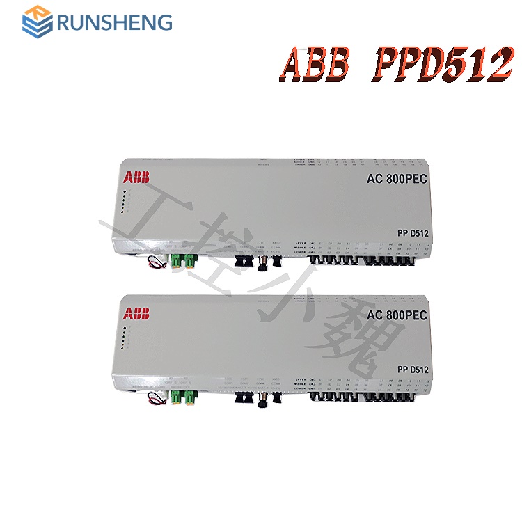
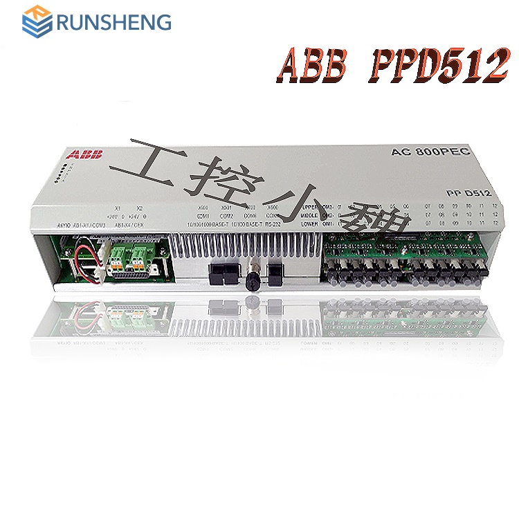
PPD512 3BHE040375R1023
PPD512A10-150000 3BHE040375R1023
PU517 3BSC980050R46
RC527 3BSE008154R1
More......
RELATED ARTICLE
PLC Dragon Automation
Address: Wanda Plaza, Chengdu, Sichuan Province
Google email: wkcarshop666888@gmail.com
Industrial Control Sales Consultant: Amelia
Whatsapp: +86 18030295882
12A3256BC9DA41BAB264DB676273DA32.png)


3BE7E049824E4F11BE61AD65D86DFEBD.png)