
How to install the ABB excitation control unit UAD149A0001 3BHE014135R0001?
Date: Nov 22, 2025Views:
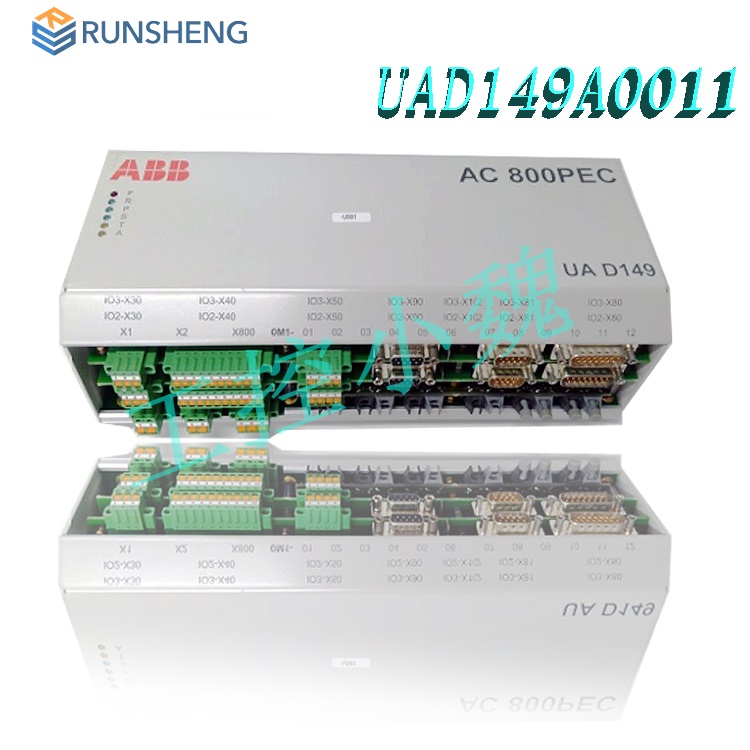
ABB Excitation Control Unit UAD149A0001 3BHE014135R0001 Installation Guide
Installation Environment Requirements
Environmental Adaptability: Must be installed in a dry, dust-free indoor environment free from volatile gases and acidic fumes. Operating temperature: -25°C to +70°C; storage temperature: -40°C to +85°C; protection rating: IP67/IP20. Avoid high temperature, high humidity, strong vibration, and corrosive gas environments. If near welding equipment, a partition must be installed.
Space and Heat Dissipation: Vertical installation is required to ensure proper cooling. Allow ≥50mm above the equipment, ≥20mm below, and ≥10mm to the sides to ensure airflow. The mounting plate must be electrically grounded (PE) using M6 screws (torque 10Nm). The grounding wire cross-sectional area must be ≥4mm², and a toothed washer must be used to ensure a good electrical connection.
.jpg)
Physical Installation Steps
Equipment Positioning and Fixing
Install the module in a standard rack or DIN rail, ensuring sufficient space for heat dissipation (≥50mm ventilation clearance) and avoiding proximity to heat sources (such as frequency converters).
Use screws to secure the module; a torque of 0.6-0.8 Nm is recommended to ensure no movement. Hot-swappable design is supported, but power must be disconnected and anti-static equipment worn before operation.
Electrical Connection Specifications
Power Connection Connect to a 24VDC power supply, paying attention to polarity (+/-). Configure redundant power input to ensure voltage stability (fluctuation ≤ ±5%).
Signal and Communication Connect to Modbus, Profibus, Ethernet, etc., using shielded cables and proper grounding (grounding resistance ≤ 1Ω) to avoid crosstalk.
Grounding Protection The module casing and grounding busbar must be reliably grounded, using the nearest grounding source to reduce loop length; use a grounding resistance tester to verify grounding effectiveness.
Software Configuration and Debugging
Parameter Settings
Configure parameters using ABB Engineering Tools, including voltage/current range, communication protocol, address mapping, and safety presets.
Supports redundancy management software, automatically detecting faults and switching to backup modules (switching time <100ms).
Debugging and Verification
Before powering on, check the tightness and insulation of all wiring. Verify the power supply voltage using a multimeter.
After powering on, observe the status indicator lights: solid green (normal power supply), flashing yellow (communication establishing), solid red (fault alarm).
Perform a full-channel seamless switching test to verify output stability and fault code parsing (e.g., Modbus exception code 2 corresponding to an illegal data address).
Physical Installation Steps
Basic Preparation: Check that the equipment model, specifications, and serial number match the order. Confirm that all components are complete and undamaged.
Fixed Installation: Select a stable, vibration-free, and easily maintainable location. Use original accessories to vertically fix the equipment to a standard rack or mounting plate. Ensure the mounting plate and equipment are properly grounded and avoid operating while the power is on.
Modular Expansion: Supports hot-swapping and redundant power supply configurations. Expandable I/O modules (e.g., DI/DO, AI/AO) or communication interfaces (e.g., Modbus, PROFIBUS, Ethernet). Compatibility verification is required (third-party devices require careful evaluation).
Electrical Connections and Configuration
Power Management: Input voltage 18VDC-160VDC, output 5VDC/10A, efficiency >90%. Redundant power supply configuration is required, with periodic voltage stability testing (fluctuation ≤ ±5%). Use power modules with overvoltage protection to avoid overvoltage, overcurrent, or short circuits.
.jpg)
Signal and Communication: Integrated 8-bit DIO, LPC, and SMBus interfaces, supporting various signal types including voltage, current, resistance, and thermocouples. Communication protocols are compatible with Modbus, PROFIBUS, Ethernet, etc. IP address, baud rate, and other parameters must be configured to ensure seamless integration with PLCs, SCADA systems, and third-party devices (e.g., Siemens, Honeywell).
Software Configuration: Parameter settings (such as voltage/current range, communication protocol, address mapping) are configured via ABB Engineering Tools, supporting seamless switching across all channels, output hold, and safety presets. Firmware updates and configuration data backups are required regularly.
Functional Testing and Maintenance
Functional Verification: Perform tests such as excitation current regulation and PID control to ensure the device responds to input signals and outputs correct control signals. Perform data transmission tests with other devices via the communication interface to integrate and adjust the entire power system.
Diagnostics and Protection: Built-in overcurrent, overvoltage, undervoltage, and overheat protection mechanisms provide error codes (such as illegal data addresses) via the Modbus protocol. Regularly check the power module temperature (≤70℃), output voltage, and connector status, and use diagnostic tools for remote monitoring.
Maintenance Guidelines: Check the device status quarterly, clean dust, and ensure good heat dissipation. Non-standard configurations (such as overclocking) are prohibited to avoid affecting system stability. Troubleshooting requires first investigating external factors, then checking internal components, and referring to the ABB manual to interpret fault codes.
Safety Operating Procedures
Personnel Qualifications: Installation, operation, and maintenance must be performed by trained and qualified professionals, adhering to local safety standards (such as IEC 60204-1 Mechanical Safety).
High Voltage Protection: When handling power modules, wear insulated gloves, use insulated tools, and ensure the equipment is powered off (verify no voltage) before operation. Do not work in thunderstorms or humid environments.
Emergency Stop: Equip the system with an emergency stop button to ensure rapid power disconnection in abnormal situations, preventing equipment damage or personal injury.
Maintenance and Safety Precautions:
Daily Maintenance: Regularly check the power module temperature (≤70℃), output voltage, and connector status. Use diagnostic tools to monitor for overvoltage, overcurrent, short circuits, and other abnormalities in real time.
Perform parameter backups and firmware updates quarterly to avoid non-standard configurations (such as overclocking).
Safety Operating Procedures:
Insulation/maintenance must be performed by trained and qualified personnel, adhering to IEC 60204-1 Mechanical Safety Standard.
Wear insulated gloves and use insulated tools when operating at high voltage. Do not work in thunderstorms.
An emergency stop button must be properly configured to ensure rapid power cut-off in case of abnormalities.
Compatibility and Expansion Configuration
System Integration: Belongs to the ABB AC 800PEC industrial automation system, supporting collaboration with AC 800PEC control boards, UAD149A0011/UAD149A0001 modules, etc., and adaptable to DI/DO and AI/AO expansions.
Expansion Limitations: Compatibility must be verified when expanding I/O modules or communication interfaces to avoid non-standard configurations affecting system stability.
Summary: The installation of UAD149A0001 3BHE014135R0001 must strictly
adhere to electromagnetic compatibility, grounding, heat dissipation, and
electrical connection specifications. Modular design and redundant configuration
ensure system reliability.
Related product recommendations:
S-093H 3BHB030478R0009
S-093M 3BHB009885R0013
S-093M 3BHB009885R0063
S-093H 3BHB009885R0005
S-093R 3BHB009885R5311
S-073N 3BHB009884R0021
S-097H 3BHB009885R0052
S-093H 3BHB030478R0309
S-053M 3BHB012897R0003
S-073N 3BHB009884R0021
S-093H 3BHB009885R0004
S-097H 3BHB009885R0052
More......
RELATED ARTICLE
PLC Dragon Automation
Address: Wanda Plaza, Chengdu, Sichuan Province
Google email: wkcarshop666888@gmail.com
Industrial Control Sales Consultant: Amelia
Whatsapp: +86 18030295882
12A3256BC9DA41BAB264DB676273DA32.png)


3BE7E049824E4F11BE61AD65D86DFEBD.png)