
FLAME TRACKERTM SiC TWO WIRE FLAME SENSOR (4-20 mA) OPERATION & MAINTENANCE MANUAL MODEL RS-FS-9001 REVISION M
Date: Sept 18, 2025Views:
SENSOR
Figure 1 is a block diagram of the SiC Flame Sensor. The sensor has a sapphire window that is transparent to UV light and can withstand the compressor discharge temperature and pressure. It has a lens inside that focuses the light on a silicon carbide photodiode in a hermetic package. The photodiode is wired to a MOSFET input amplifier. The amplifier has a high initial gain, which automatically shifts to a lower gain in order to accommodate a wide range of input light level without saturating. The sensor regulates the supply current in proportion to the amount of UV light present. Both power and signal are transmitted on the same two wires. The sensor can be powered from a dc voltage between 12 and 30 volts. The whole transducer is sealed and filled with dry argon.
MECHANICAL
The maximum operating temperature for the flame sensor is 302 F (150 C). If the peak ambient temperature at the location of the sensor exceeds this then cooling will be required. There are three methods available for cooling: Water-cooling, air-cooling with ambient air, and air-cooling with pressurized air.
Water cooling requires the use of a water cooling coil Part Number sp-566, GE Part Number 353B3490G001. The water-cooling coil requires water at a temperature of 50 F to 135 F (10 C to 57 C) at a flow rate of 1.0 gpm (3.8 lpm) per sensor. When using water-cooling the flame sensor can be operated to an ambient temperature of (455F) 235C.
Air-cooling with ambient air can be used in installations where the enclosure is cooled with forced air. This would be typical of LM2500 and LM6000 aircraft engine applications. The air velocity at the sensor must be 5 ft/sec (1.5 m/sec), or greater, at a temperature of 50 F (10 C), or less, above outside ambient. Under these conditions the sensors will operate at outside ambient temperatures up to 140 F (60 C).
Air-cooling with pressurized air requires the use of Air-Cooling Can. GE Reuter-Stokes Part Number RS-E2- 0259 (GE Part Number 07482SOCNL44821P01). The Air-Cooing Can is installed in the same manner as the water-cooling coil. The Air-Cooling Can requires 25-psi (170 kPa) minimum at 120 F (49 C) maximum.
Do not complete step 2 in the “FLAME SENSOR AND WATER COOLING JACKET INSTALLATION INSTRUCTIONS” on the next page. Leave the sensors installed hand tight until after the sensor checkout described in Section 3.3.
1. Apply a small amount of Never-Seez PN NG-165 (GE PN 248A9779P001) to threads, prior to reinstalling the Flame Sensor
2. Inspect the window and clean with Isopropanol soaked swab. If required install hand tight (3-4 Full turns) tighten with a wrench approximately 2.5 turns. Tighten further as required to align keys on cable connector with slots in sensor connector
.jpg)
3. Slide cooling coil over Flame Sensor major diameter and orient tubes on the coil as required for assembly. Tighten clamps 50-60 in. lbs. Install Swagelok fittings re-torque clamps to 50- 60 in. lbs. after first shut down
ELECTRICAL
The sensors are connected to the turbine junction box with connector cable RS-E2-0285 or equivalent. The RS-E2-0285 consists of black, white and green wires twisted and shielded. All wiring must be in grounded conduit. The green wire must be connected to earth ground at the junction box. Do not connect the shields to each other or to earth ground at any location. The shields should be individually jumped through all junction boxes and connected to the proper ground terminal at the Controller. The polarity of the cable is as follows; white is positive and black is negative/signal return. Reverse polarity will not damage the sensor. Signal cable from the junction box to the Controller should be 18 gauge (1.02 mm) twisted shielded pair. The extension cable from the junction box to the Controller is the customer’s responsibility
The Flame Tracker™ is connected to the controller as a typical two wire current transmitter. It can be operated from any well-filtered dc supply from 12 volts to 30 volts. The supply should be capable of supplying 100 milliamps.
The power supply must be protected to prevent the supply voltage from exceeding 30 volts in normal use and more than 42 volts under transient conditions. The sensor is protected against reverse polarity. The maximum value for the sense resistor plus the wire resistance is dependent on the supply voltage. At 24 volts this value is 560 ohms. Resistance values for other voltages can be determined from the chart in Figure 2.
Figure 1 shows the preferred wiring for the sensor with the Rsense of the controller in the return line of the sensor. This configuration can be used with controllers that have single ended inputs (one side of the input grounded) or differential inputs (neither side of the input grounded). For pin outs and cable color code see Figure 1.
.jpg)
SENSOR CHECKOUT
Disconnect the sensors and unscrew them from the turbine. Plug the sensor cables back in to each of the sensors. Apply power to the sensors. Check the current values at the controller for each of the sensors. The sensors are sensitive to light, and may have some reading, depending on the ambient light level. Test each sensor by covering the port to see the zero flame intensity signals, and with a flashlight to see a positive reading. With no light the reading should be 3.7 to 4.1 milliamps, while with most flashlights the reading should be above 8 milliamps. An LED flashlight may not work for this application. Variations in flashlight type, strength, or battery voltage may cause variation in signal output. The flashlight test is intended as a field test for general functionality only and is not a controlled or quantitative test. If a sensor is outside these rough check limits see Section 5.0.
Disconnect the sensor cables, and reinstall the sensors according to the instruction in Section 3.1. At this time step 2 of Section 3.1 should be completed and the sensor cables reconnected. Make sure that the sapphire window is clean; if it needs cleaning, do this according to the maintenance instructions in Section 4.0. Check that all sensors are reading between 3.7 to 4.1 milliamps.
CONTROLLER SETUP
The Flame Sensor provides a minimum output of 5 milliamps when exposed to the minimum flame intensity specified in GE specification number 362A1052. The set point for flame off should be set to 6.25%, which equals 5 milliamps. The set point for flame on should be 10%, which equals 5.6 milliamps. If the intensity levels are to low for these settings their may be other problems. Low intensity levels may be a sign of other problems. Refer to Section 5.0 - Troubleshooting.
Related product recommendations:
RS-FS-9004
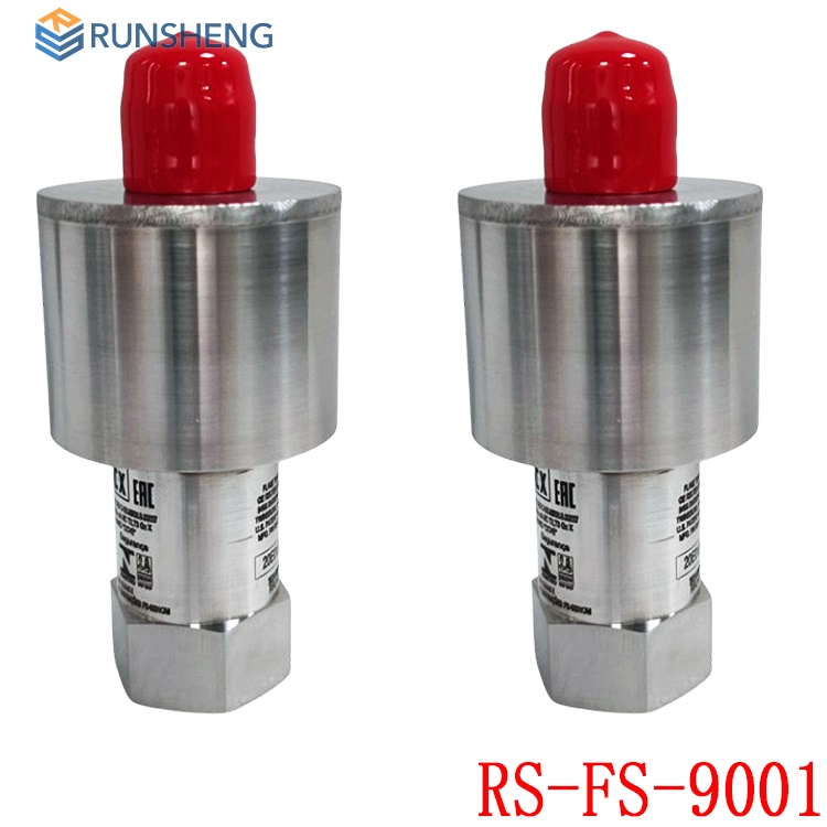
RS-FS-9001
IOC-555-D 17-550555-001
PSMU-350-3 CPCI-350Q-P-38
TIOC-555HD
MCP-1004
TMPU-1002
TIOC-555HD
PSMU-350-3
05701-A-0282
05701-A-0145
05704-A-0146
05704-A-0123
05701-A-0294
05701-A-0288
05701-A-301ISS
05701-A-0283
05701-A-0327
05701-A-0451
05701-A-0301
CC-TAIN11 51306515-175
CC-TAIX51 51307075-175
SC-UCMX02 51307195-276
SC-UMIX01 51307547-175
CC-PUIO01 51454205-175
CC-PCNT02 51454551-275
51410069-275
CC-PAIH51 51410069-275
0571-A-0325
More......
RELATED ARTICLE
PLC Dragon Automation
Address: Wanda Plaza, Chengdu, Sichuan Province
Google email: wkcarshop666888@gmail.com
Industrial Control Sales Consultant: Amelia
Whatsapp: +86 18030295882
12A3256BC9DA41BAB264DB676273DA32.png)


3BE7E049824E4F11BE61AD65D86DFEBD.png)