
nstructions for installation, operation, and maintenance of the SL 15 kV, 300A vacuum contactor-SL72S4SH3LANL7MNR25
Date: Jul 31, 2025Views:
The SL contactor weighs about 95 pounds. It should be handled gently to avoid damage to the vacuum bottles and factory adjustments.
The contactor is designed to be mounted in a medium voltage starter with overload relays and power fuses. In a factory assembled starter, the contactor is ready for service except for routine check-out as described in the InitIal setup section.
The contactor should be mounted inside an enclosure that protects the unit from adverse environments such as dust and water. The mounting surface should be flat and horizontal, with provision for securely bolting the contactor in place with four 5/16-inch x 18 bolts.
The mounting holes are located in side panels on the contactor as shown in the top view in Figure 1.
Contactor operation
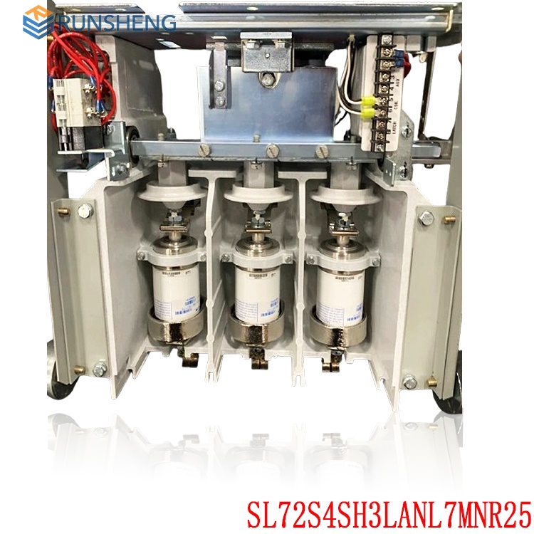
The SL contactor has its main contacts sealed inside ceramic tubes from which all air has been evacuated, i.e., the contacts are in vacuum. The arc simply stops when the current goes through zero as it alternates at line frequency. The arc usually does not survive beyond the first half cycle after the contacts begin to separate. The ceramic tube with the moving and stationary contacts enclosed is called a vacuum interrupter or a vacuum bottle and there is one such bottle for each pole of the contactor. A metal bellows (like a small, circular accordion) allows the moving contact to be closed and pulled open from the outside without letting air into the vacuum chamber of the bottle.
The moving contacts are driven by a molded plastic crossbar rotating with a square steel shaft supported by two shielded, pre-lubricated ball bearings that are clamped in true alignment for long life and free motion. See Figure 2. Only the end edges of the square shaft are rounded to fit the bearings, so that portions of the four shaft flats go through the bearings for positive indexing of the mechanical safety interlocks.
.jpg)
The contacts in an un-mounted vacuum bottle are normally closed, because the outside air pressure pushes against the flexible bellows. For contactor duty, the contacts must be open when the operating magnet is not energized. Therefore, the contacts of the vacuum bottles must be held apart mechanically against the air pressure when used in a contactor. In the SL contactor, all of the bottles are held open by two kickout springs on the front of the contactor. See Figure 2. The kickout springs press against the moving armature and crossbar and thereby force the bottles into the open contact position. Note that in the open position, the crossbar is pulling the moving contacts to hold them open.
Up to an altitude of 3300 feet, the contactor is designed to tolerate normal variations in barometric pressure.
.jpg)
The contact force at sea level when fully closed is intended to be 65 to 75 pounds. This will decrease approximately 0.75 pounds per 1000 feet above sea level. If the contact force is below 65 pounds, contact the factory.
The contactor is closed by energizing the contactor control board with the appropriate control voltage at terminals 1 and 2. The control board rectifies the input voltage and applies a pulse width modulated DC output voltage to the coil. The output voltage is approximately full voltage for the first 200 milliseconds after energization, during which time the contactor closes and seals. The output voltage is then automatically reduced to approximately 15 Vdc to maintain the contactor in the closed position.
The coil core is magnetized, which rotates the armature shaft, armature, and crossbar. As the armature moves toward the coil core, the main contacts close. The crossbar continues to move an additional distance (known as overtravel), which allows for contact preload and wear. The overtravel distance is the gap between the lower bottle nut and the pivot plate as shown in Figure 4.
When control power is removed from the control board, the contactor is held closed for a preset time and then opens. The range of time between the removal of control power and contact opening is from 50 to 330 milliseconds. The time can be adjusted for such factors as fuse coordination and voltage loss ride-through. Unless otherwise specified, the factory default dropout setting is 130 milliseconds, or approximately 8 line cycles (60 Hz).
A selectable DIP switch for setting the control voltage level and the contactor dropout time is located on the control board. See Figure 5. The control board must be removed from the cavity in the contactor housing to gain access to the DIP switch. Table 3 lists the available voltage settings and Table 4 lists the available dropout settings. These tables are also printed on the back of the control board.
.jpg)
Initial setup
Check-out, mechanical
Verify that all power circuits are de-energized and/or isolated. The contactor can be checked in its cell or outside. If the starter is a new factory assembly, it is probably easiest to test the contactor as installed. Any mechanical interlocks must be checked as installed, to make certain that safety interlocks function properly
If the contactor is checked in its cabinet, verify that the contactor coil is electrically isolated, to prevent feedback into a control transformer that could be hazardous.
With an extension cord and a separate power source of correct AC voltage, connect power to the control board of the contactor. Operate the appropriate pushbuttons to close and open the contactor, and to check out the sequence. If the contactor does not close fully or does not drop out fully, refer to Magnet operating range in the Maintenance section.
When the contactor is closed, observe the overtravel gap between the pivot plates on the crossbar and the underside of the lower bottle nut on each pole. This overtravel gap should be no less than 0.100-inch when the contactor is new.
When the contactor is open, the armature plate should be firmly seated against the contactor housing.
Disconnect extension cord and proceed with installation.
The dielectric strength of the interrupters should be checked before the contactor is energized for the first time and regularly thereafter to detect at the earliest possible date any deterioration in the dielectric strength of the contact gap because this may result in an interruption failure. Although an AC dielectric test is recommended, a DC test may be performed if only a DC test unit is available. A good interrupter will withstand a 36 kV–60 Hz test or a 50 kV–DC test across the open gap for one minute. When performing DC tests, the voltage should be raised to the test value in discrete steps and held for a period of one minute. Due to the high voltage levels required to conduct this test, it is recommended that the contactor be removed from the starter cell before beginning the test.
Check-out, insulation level
After installation and before energizing the contactor for the first time, the dielectric test levels between poles and from each pole to ground should be measured and recorded. Conduct testing at a value of two times the nominal voltage.
Maintenance
A maintenance program should be established as soon as the contactor is installed and put into operation. After the contactor has been inspected a number of times at monthly intervals, and the condition noted, the frequency of inspection can be increased or decreased to suit the conditions found, because this will depend upon the severity of the contactor duty. It is a matter of operator judgment.
All work on this contactor should be done with the main circuit disconnect device open and locked out, and by using a separate source of control power to operate the magnet. Before applying external control circuit power, verify that the contactor coil circuit is electrically isolated, to prevent feedback into a control transformer that could be hazardous. Disconnect power from any other external circuits.
Related product recommendations:
UNIOP eTOP307-U101
UNIOP ETOP310
UNIOP ETOP02C-0046
UNIOP eTop05EB-11E50
UNIOP ETOP12-0050
UNIOP ETOP507U3P3
UNIOP ETOP03-0045
UNIOP eTOP20B-0045
UNIOP ETOP33C-0050
UNIOP eTOP20B-0050
UNIOP ETOP40-0050
ALSTOM ICP232-8DI/8DO
ALSTOM ICP232-16DI/16DO
ALSTOM ICP232-ETH
ALSTOM SPU232.1
ALSTOM SPU232
ALSTOM ICP232 029.359325
ALSTOM ICP232
ETOP306U201 UniOP
More...
RELATED ARTICLE
PLC Dragon Automation
Address: Wanda Plaza, Chengdu, Sichuan Province
Google email: wkcarshop666888@gmail.com
Industrial Control Sales Consultant: Amelia
Whatsapp: +86 18030295882
12A3256BC9DA41BAB264DB676273DA32.png)


3BE7E049824E4F11BE61AD65D86DFEBD.png)