Control Terminals
The control terminations for the MVR1600-4601-A, which are made via TB1,
are suitable for 0.5mm² to 2.5mm² size wire (20- 14 AWG).
AC Line Reactor / DC Link Inductor Details
These components are application dependent and are thereforenot specified
inthis data sheet.
Commissioning
Refer to the WARNINGS and CAUTIONS in the relevant Manua(s).
Commissioning of the unit is dependent upon the application of the unit.
Refer to the relevant manual(s) for details of the commissioning procedure.
Introduction
The MVRL2100-4601-A is manufactured by Avid Controls under license from the General Electric Company.
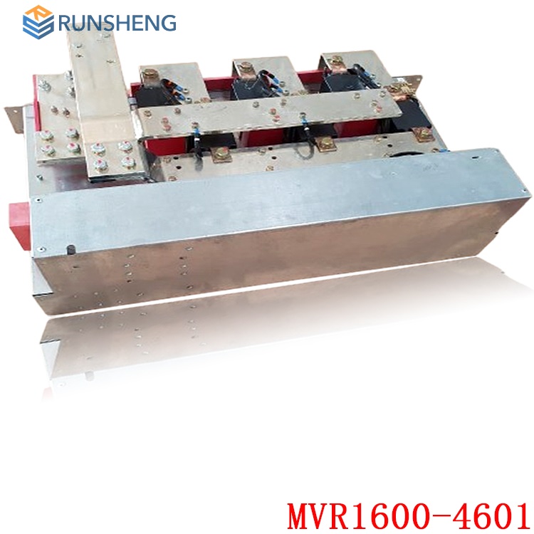
In an MV3000 DELTA drive system, rectifier modules shown below are used in network bridges to convert an AC supply into a rectified, unsmoothed DC supply.
The rectifier module may be operated as a 12-pulse network bridge. This configuration is achieved by connecting the DC positive outputs together through an inter-bridge transformer and one AC input being phase-shifted in relation to the other by an external supply transformer.
.jpg)
Features
The rectifier module includes a circuit which is capable of pre-charging the transistor modules. This circuit charges the DC link capacitors of the transistor modules via current limiting resistors in the rectifier module.
Modules fit in the standard DELTA mounting frames.
Metal oxide varistors are included to absorb surge energy from the mains. Supply impedance is necessary for this to function correctly.
Protection against DC link short circuits is with the use of recommended semi-conductor fuses.
Modules carry thermostat and thermistor temperature sensing devices, which are monitored by the MV3000e controller to provide over-temperature protection.
Interfaces
Signals between the controller and rectifier module are by individual wires.
The AC and DC power connections have stud terminals and are designed for cable connection.
.jpg)
External Requirements
For parallel operation of rectifier modules, external sharing reactors must be fitted;
Similarly, for parallel operation of the two six-pulse rectifiers within a MVRL2100-4601 module, external sharing reactors must be fitted;
For 12-pulse operation, the two supplies must be phase shifted by 30° to each other, and be of balanced voltage. The DC output must be through an inter-bridge transformer;
Protection of the main input rectifier devices is by the addition of external semi-conductor fuses. For recommended fuses, see FUSES section. The AC and DC terminals on the modules are not suitable to support the weight of any attached cables. These cables must have additional mechanical support;
These liquid cooled modules must be cooled by an externally derived cooling system.
Electrical Connections
Power Connections
The AC and DC terminals on the modules are not suitable to support the weight of any attached cables. These cables must have additional mechanical support.
The bending radii limits of all cables must be respected.
AC and DC Power connections are based on High Temperature Cable, e.g. Von Roll Isola silicone rubber type SIWO-KUL or equivalent.
AC Terminals
All AC power terminals are located on the front of the module and are marked R1, S1, T1 and R2, S2, T2.
Each terminal provides two M10 studs which are suitable for ring-crimp connection.
Maximum 2 x 150mm2 cable per phase.
DC Terminals
The DC terminals are located on the lower right-hand side of the module.
Each DC positive connection, marked RECT1 + and RECT2 +, have two M10 studs.
The DC negative connection, marked RECT1/2 -, has four M10 studs.
Maximum 150mm2 cable per connection.
Control Connections
The rectifier control terminals are mounted at the top of the front face of the Rectifier module as below. The customer terminals are the left half of a 10-pin plug and socket, referenced TB1, and may be unplugged for ease of wiring.
Terminals will accept up to 2.5 mm2 (12 AWG) flexible cables. To prevent failure of the Rectifier module pre-charge components, the rectifier pre-charge acknowledge signal (TB1/9) must be connected to the control module. If this signal is not healthy the control module will not allow the drive to run.
Recommended products:
IC695ALG508-AA
IC3500A452L208
DS3800HFPB1F1E
DS3800NB1F1B1A
DS3800DIC1D1B
IS210BPPBH2BMD
DS3800HI0C1L1H
DS3800HIOC
DS3800HFPB1F1E
IS200WREAS1ADB
IS200AEPAH1ACB
IS200AEPAH1AFD
IS210MACCH2AGG
IS210MACCH2AEG
IS200AEPCH1ABC
IS200BPPBH2CAA
More......

12A3256BC9DA41BAB264DB676273DA32.png)


3BE7E049824E4F11BE61AD65D86DFEBD.png)