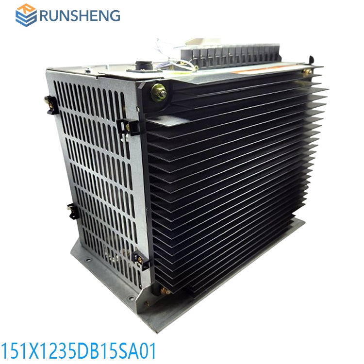
151X1235DB15SA02 EX2100E Regulator PCM
Date: Dec 19, 2024Views:
The EX2100e Excitation Control Regulator system is GE’s most recent state-of-the-art control system for steam, gas, or hydro generators for both new and retrofit units. Control hardware and software design is closely coordinated between GE’s system and controls engineering to ensure delivery of a true system solution. Integration is seamless between Excitation Control systems, Turbine Control systems, Static Starter Control systems, Integrated Control Systems (ICS), and the Human-machine Interface (HMI). For stand-alone retrofit applications, integration with customer distributed control systems (DCS) through serial or Modbus® Ethernet is supported. This document specifically addresses applications for the 35 A and 120 A (nominal) series of EX2100e Control Regulator systems.
Control Hardware
The EX2100e Regulator system is available in several configurations to provide control flexibility for Thyristor and Regulator systems. For small Regulator systems, two pulse-width modulated (PWM) power converter modules use Insulated Gate Bipolar Transistors (IGBT) to provide up to 35 A or 120 A nominal output. These systems can support the following applications:
.jpg)
• Saturable Current Transformers / Power Potential Transformers (SCT/PPT) regulator
• Brushless exciter regulator
• Direct current (dc) rotating exciter regulator
In the SCT/PPT regulator and dc rotating exciter regulator applications, the EX2100e Regulator system can de-sensitize the effect of the exciter time constant. It incorporates direct measurement of the generator field voltage and field current to enhance speed of response to system transients.
The architecture is a single control with a single Power Control Module (PCM) or dual control with dual PCM, including a customer interface sub-system, optional diagnostic local operator interface (touchscreen), optional control operator interface (COI) remote touchscreen interface, control power input module, and PCM. The PCM consists of a bridge interface sub-system, power bridge, optional ac and dc filter networks, and alternating current (ac) and/or dc isolation devices. For expanded input and output (I/O) capability, either VersaMax® or Mark* VIe control IONet I/O modules may be added.

The EX2100e Regulator system supports Ethernet local area network (LAN) communication to the following:
Turbine controls and ICS, HMI, Proficy*-based Historian, Programming Interface (PI-based) Historian, Onsite Monitoring System (OSM), and COI
• Extended I/O modules using the Ethernet Global Data (EGD) protocol
• Customer DCS through Ethernet or Modbus Ethernet remote terminal unit (RTU)
• ToolboxST* application
• GE Onsite Support* for monitoring and diagnostics
Digital Controller (IGBT-based Systems)
The EX2100e Excitation control products offer a Regulator control system in a 800 mm (32 in) enclosure with supporting hardware based on the particular application. Other packaging options are available. The Regulator system can be purchased as part of a finished cabinet, or individual components can be shipped separately for onsite mounting to better serve retrofit applications.
Power conversion consists of an input section, a dc link, and the converter output section. The input section is a 3-phase diode bridge with input filters. The system accepts a primary ac input range of 90 to 280 V rms, nominal for the 35 A system, and up to 480 V rms for the 120 A system. The ac input is 480 Hz (maximum), which can be supplied as 1-phase or 3-phase from a permanent magnet generator (PMG), auxiliary bus, or generator terminals.
As a backup, the system accepts a secondary power input from a dc battery bank (125 to 250 V dc nominal). The dc secondary input is diode-isolated and combined with the 3-phase diode bridge output. These sources energize the dc link, which is an unregulated source voltage for the control output power through the IGBTs. The dynamic discharge (DD) circuit limits the dc link voltage level during events such as load rejection or unit trip.
.jpg)
The converter output section uses IGBTs to pulse-width modulate the dc link source voltage to its final value. The chopping frequency of the IGBTs is approximately 1,000 Hz. This output is fed to the exciter field as a regulated voltage or current. An output shunt monitors the field current. Continuous dc output is provided up to 100% rating with temporary forcing capabilities up to 210%. Regulated output flows through a dc contactor to the exciter field.
The EX2100e Regulator system contains interface boards that are interconnected through a high-speed serial link (HSSL) and cabled to their associated I/O terminal boards.
Dual Control (Power Bridge Warm Backup)
The EX2100e Regulator system is available in a warm backup (WBU) configuration, which includes dual exciter control I/O and protection. The control includes M1 (Master One) and M2 (Master Two), with two IGBT bridges that can accept separate or shared ac input power. The control configuration can also share a common dc output circuit to the exciter field through the transfer module. M1 and M2 are independent controls, each with automatic and manual regulator functions. Either M1 or M2 can control bridge firing, as determined by the operator. In the WBU configuration, M1 controls bridge #1, and M2 controls bridge #2.
To process application software, two independent Universal Controller Stand-alone Board Version B (UCSB) controllers, with separate PCMs and an output selector module (SCM or TCM), provide the dc output current for the exciter field (or SCT control winding).
The active power bridge receives the gating commands from the active control (M1 or M2), and supports the full-field voltage and current needs of the exciter field while the backup power bridge’s gating circuit is inhibited. The operator has full control to select which of the dual power bridges is active or inactive. Bi-directional, bumpless transfer between active and inactive bridges is standard. The active master can also self-diagnose a failure or missed operation and activate the backup control and power bridge without operator intervention.
Control Cabinet
The EX2100e Regulator system is encased in a NEMA® 1/IP20 or IP21 freestanding, indoor metal cabinet for floor-mounting installation. An IP54 option for the cabinet is also available. The standard cabinet color is ANSI-70 (light gray) on exterior surfaces (other colors are available). Interior surfaces are galvanized steel. The equipment is designed to operate in an ambient temperature range of 0 to 40°C (32 to 104 °F). Depending upon the specific application, a current derating factor may apply at 50°C (122 °F).
Power Conversion Module
The Power Conversion Module (PCM) consists of an integrated IGBT inverter module that contains six IGBTs connected in a 3-phase inverter configuration. Two of the six IGBTs are used to create the PWM dc output for field excitation. A third IGBT is used to discharge the dc link capacitors into an external DD resistor to prevent overvoltage.
Input power is either rectified ac, dc from a station battery, or both. In the dual redundant application, there is a primary control and PCM (M1) and a backup control and PCM (M2), which are identical. A transfer module evaluates the health of the primary and backup controls and selects which control is active to provide maximum reliability and availability.
Control Software
The EX2100e control software supports high performance and helps the customer and field engineers understand, install, commission, tune, and maintain the excitation control system. The exciter software is configured and loaded from the ToolboxST application and resides in the controllers. The software is represented on the ToolboxST Component Editor screen by control blocks that are linked together to display the signal flow.
The generator voltages and currents from the PTs and CTs are the source of the control signals needed by the automatic (generator terminal voltage) regulator, most limiters, and protection functions. They are wired to the ESYS, which acts as a signal conditioner to isolate and scale the signals. The conditioned signals are fed to the controller. The system simultaneously samples the ac waveform at high speed and uses advanced mathematical algorithms to digitally generate the needed variables.
The output of the software transducer system includes the following:
Generator voltage
Generator active current (average in phase with watts)
Generator reactive current (average in phase with reactive power, VARs)
Generator frequency (current)
Slip (signal representing the change in the rotor speed)
The transducer system uses the output to calculate the following:
• Generator power and VARs
• Magnitude of generator flux (V/Hz)
• Phase angle and power factor
The following figures provide a simplified overview of the exciter control system, displaying the main control functions. Both the generator field and stator currents and voltages are measured and input to the control system. In normal operation, the ac regulator is selected.
IS200TRPGH1B
IS200DAMAG1A
IS200DAMAG1ACA
IS200VGENH1BCB
IS200VPWRH1AJD
IS200TRLYH1FAA
IS200UCVIH1AEC
IS200VVIBH1C
IS200ATBAG1BAA1
IS200EBR2AEX2100E
IS200AEBBMG1AEB
IS200VSVOH1BDC
IS200DSCBH1ABB
IS200EPSMG1ABB
IS200VTURH1BAA
IS200TDBSH2AAA
IS200TRLYH1BHH
IS200WETAH1AEC
IS200AEPAH1AHD
IS200WEMAH1AEA
IS210MACCH1AGG
IS230TNRLH1B
IS200VSVOH1BED
More......
RELATED ARTICLE
Shanxi Runsheng Import and Export Co., Ltd
Address: 3301, Building A, Wanda Center, No. 175 Jiefang Road, Xinghualing District, Taiyuan City, Shanxi Province
Google email: wkcarshop666888@gmail.com
Industrial Control Sales Consultant: Amelia
Whatsapp: +86 18030295882

