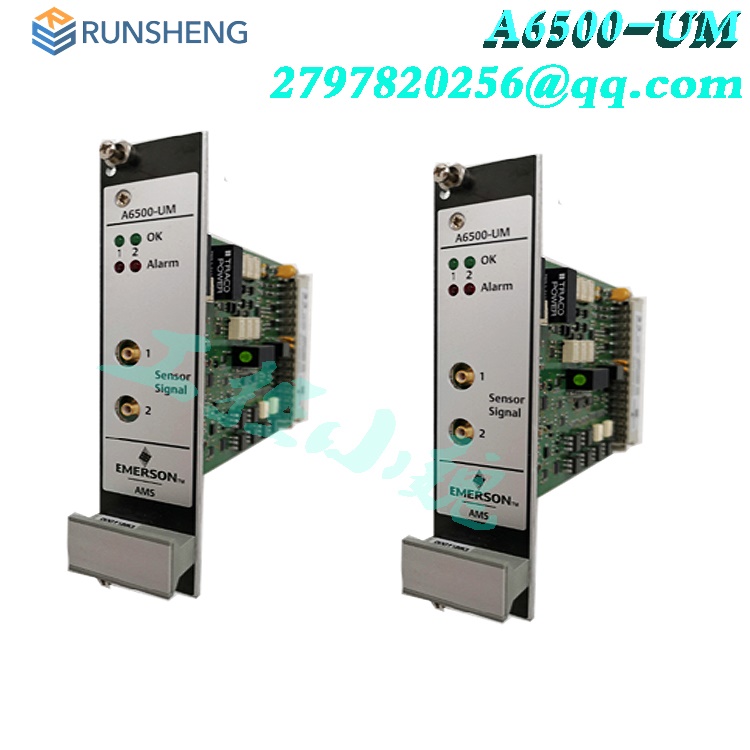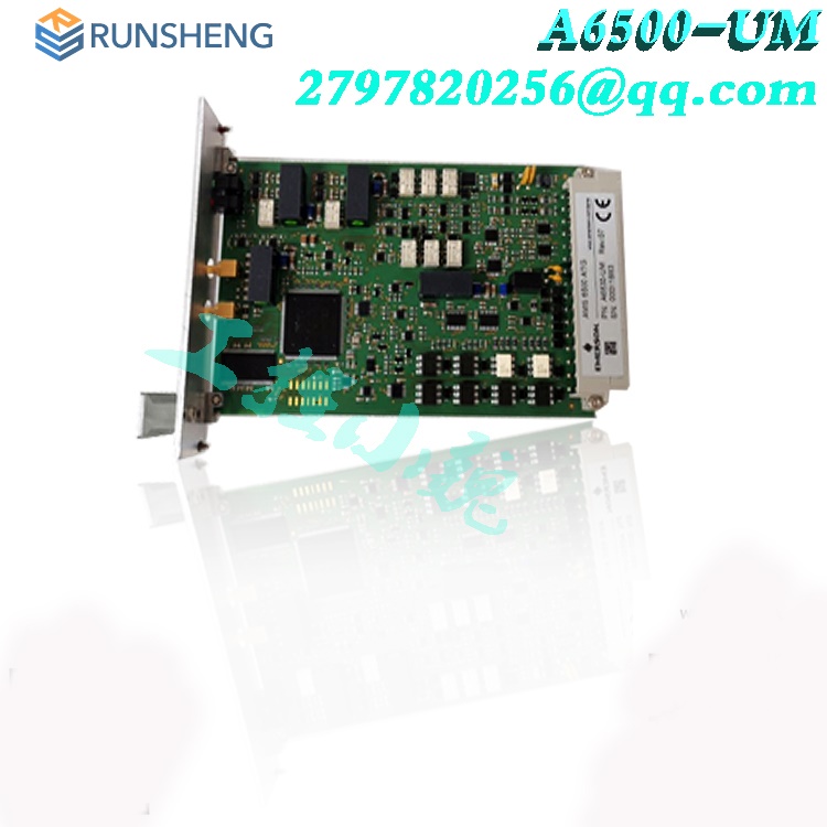
Machinery Health™ System A6500-RC Relay Card
Date: Aug 09, 2024Views:
Application
The A6500-RC Relay Card is a component of the AMS 6500 ATG machine protection system. It is a freely programmable microprocessor-controlled module that can be used to do logical combination of binary signals within a AMS 6500 ATG system. When connected to an A6500-xR System Rack, the measurement cards provide and connect their logical outputs (COK, Alert, and Danger) automatically tothe A6500-RC inputs through the backplane of the System Rack.
The A6500-RC captures the signals to logically combine them and provide the results through relay outputs. The A6500-RC is intended to be used in an A6500-xR System Rack (A6500-SR, A6500-RR, or A6500-FR) which is equipped with a separate slot for the A6500- RC.
The A6500-RC Relay Card is equipped with 66 digital, galvanically separated input channels (24 V logic), 16 output relays, one green system status LED and 16 yellow relay status LEDs on the monitor front to indicate the output relay statuses. All 66 input channels can be used separately and can thus be combined with each other individually. The 16 output relay channels are designed as single-pole switchover contacts (SPDT). Connection of external digital signals is possible if using an A6500-RR system rack or an A6500-FR system rack. The A6500-RC card is not mandatory for the operation of an AMS 6500 ATG.

In conjunction with the A6500-CC Com Card status data of the A6500-RC can be provided through Modbus RTU, Modbus TCP/IP and OPC UA. As the Relay Card is designed for use with A6500-xR System Racks , generally a Com Card is required for configuration purposes.
Design
The A6500-RC Relay Card is designed as a double-standard Euro card (100 mm x 160 mm). The mechanical dimensions of the card match the dimensions of corresponding A6500-xR System Racks exactly. The front plate dimension of the A6500-RC is 3RU height and 10HP width. As the A6500-RC is manufactured in sandwich board design, the main board is equipped with a 96-pole terminal connector and the relay board is equipped with a 48- pole terminal connector (IEC 60603-2, F 48 M) to connect the respective backplane slot. Figure 3-1 shows the side view of the Relay Card.
Installation
For installation and mounting of the A6500-RC into an A6500-xR System Rack the relay output terminals and wiring are described in the operation manual of the A6500-xR System Racks. The Relay Card can be only installed in the double slot 12 (12.1 and 12.2) of the A6500-SR System Rack or in the double slots 10 (10.1 and 10.2) and 11 (11.1 and 11.2) of the A6500-RR System Rack.
Note
The AMS 6500-ATG cards are hot-swappable. So it is not necessary to switch off the power supply of the system rack for installing or replacing cards.
Procedure
1. Wire the relay output contacts of the slot in accordance to the required application.
2. Push the A6500-RC into the prepared slot 12 (12.1 & 12.2). The interconnections to the digital outputs of slots 1 to slot 11 are already done through the backplane.
3. Secure the card by gently fastening the screws at the front plate.

CSA - General safety
Conditions of acceptability See chapter "CSA - General safety" of the A6500-xR System Racks operating manual (MHM-97877) for conditions of acceptability.
Commissioning
Procedure
1. If the card is not configured, create a configuration with the AMS Machine Studio software and download it to the card (see Configuration).
2. Ensure proper work by checking input and output signals (see Functional check).
Hazardous location installation
The ex-approval of the A6500-RC Relay Card is only valid if the Relay Card is installed in an A6500-xR System Rack. See chapter "Hazardous location installation" of the A6500-xR System Racks operating manual (MHM-97877) for details.
General configuration procedure
The configuration can be performed offline, that means without connection to the card or online with a connection to the card. In any case, the configuration has to be loaded into the card. TheA6500-CC Com Card is required for the configuration procedure. See Com Card operating manual for details. Requirements:
A6500-CC Com Card (only online configuration)
A6500-RC Relay Card installed in an A6500-xR System Rack (only online configuration)
Power supply (only online configuration)
USB cable with Type-A and Type-B plug or Ethernet cable (only online configuration)
AMS Machine Studio (configuration software)
PC or laptop with Microsoft Windows 10
Offline configuration
Procedure
1. Start AMS Machine Studio.
2. Enter configuration parameter according to the task.
3. Save the configuration.
Later, load the configuration to the card when you can connect to the card.
Send a saved configuration file to the card
Procedure
1. Switch on the power supply of the system if not already on.
2. Connect the laptop to the Com Card of the system by using the USB or Ethernet connection.
3. Start AMS Machine Studio.
4. Select the Relay Card and click Configure.
5. Open the saved configuration file (window File, menu item Open) .
6. Send the configuration to the card.
7. Close AMS Machine Studio and disconnect the connection to the Com Card.
After these steps, the Relay Card is ready for operation.
More details:
![]() a6500-rc-system-relay-card-en-9881078.pdf
a6500-rc-system-relay-card-en-9881078.pdf
Related product recommendations:
A6500-RC16
A6500-TP
A6500-RR
A6500-LC
A6500-CC
A6500-SR
A6500-FR
A6120
A6110
A6140
A6312/06
A6220
A6210
A6370D
A6410
A6740
more......
RELATED ARTICLE
Shanxi Runsheng Import and Export Co., Ltd
Address: 3301, Building A, Wanda Center, No. 175 Jiefang Road, Xinghualing District, Taiyuan City, Shanxi Province
Google email: wkcarshop666888@gmail.com
Industrial Control Sales Consultant: Amelia
Whatsapp: +86 18030295882

