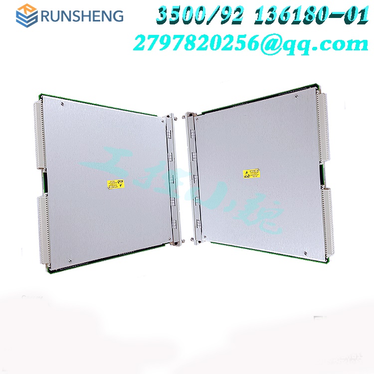
3500/22M Transient Data Interface Module
Date: Aug 09, 2024Views:
Description
The 3500/22M Transient Data Interface (TDI) is the interface between the 3500 monitoring system and compatible software (System 1 Condition Monitoring and Diagnostic software and 3500 System Configuration software). The TDI combines the function of a 3500/20 Rack Interface Module (RIM) with the data collection capability of a communication processor such as TDXnet.
The TDI resides in the slot adjacent to the power supplies of a 3500 rack. It interfaces with M series monitors (3500/40M, 3500/42M, etc.) to continuously collect steady state and transient dynamic (waveform) data and pass this data through an Ethernet link to the host software. Refer to the Compatibility section at the end of this document for more information.
Static data capture capability is standard with the TDI. However, using an optional Channel Enabling Disk will allow the TDI to capture dynamic and high-resolution transient data as well. The TDI incorporates the communication processor function within the 3500 rack.

Although the TDI provides certain functions common to the entire rack, it is not part of the critical monitoring path and has no effect on the proper, normal operation of the overall monitor system for automatic machinery protection. Every 3500 rack requires one TDI or RIM, which always occupies Slot 1 (next to the power supplies).
I/O Module Signal Common Terminal
Both versions of the TDI I/O Module now include a 2-pin connector for connecting Signal Common to a single point Instrument Ground for the rack. When this is done, the selector switch on the side of the Power Input Module (PIM) must be slid in the direction of the arrow marked "HP" to isolate Signal Common from chassis (safety) ground.
Data Collection
Keyphasor Inputs
Supports the four 3500 system Keyphasor signals. The speed range support is based on the number of dynamic channels enabled:
Supports multiple events per revolution speed inputs up to 20 kHz
.jpg)
Startup/Coastdown Data
Data collected at selected increments of speed and time
Increasing and decreasing speed intervals are independently programmable
Initiation of transient data collection based on detecting the machine speed within one of two programmable windows
The number of transient events that can be collected is only limited by the available memory in the module
Alarm Data Collection
Pre- and post-alarm data
Static values collected at one second intervals for 10 minutes before the event and 1 minute after the event
Static values collected at 100 ms intervals for 20 seconds before the event and 10 seconds after the event
2.5 minutes of waveform data collected at 10-second intervals before the alarm and 1 minute of waveform data collected at 10-second intervals after the alarm
Static Values Data
TDI will collect the static values including the values measured by the monitors.
TDI provides four nX static values for each point. Amplitude and phase are returned for each of the values.
Waveform Sampling
Collection of waveforms for 48 channels.
.jpg)
DC-coupled waveforms
Simultaneous Synchronous and Asynchronous data sampled during all operational modes
User-configurable Synchronous
waveform sampling rates:
1024 samples/rev for 2 revolutions
720 samples/rev for 2 revolutions
512 samples/rev for 4 revolutions
360 samples/rev for 4 revolutions
256 samples/rev for 8 revolutions
128 samples/rev for 16 revolutions
64 samples/rev for 32 revolutions
32 samples/rev for 64 revolutions
16 samples/rev for 128 revolutions
Asynchronous data sampled to support an 800-line spectrum at the following frequency spans:
10 Hz
20 Hz
50 Hz
100 Hz
200 Hz
500 Hz
1000 Hz
2000 Hz
5000 Hz
10 kHz
20 kHz
30 kHz
Asynchronous data is anti-alias filtered
Channel Pairs for providing Orbit or synchronous full spectrum presentations can be split among multiple monitors. For asynchronous full spectrums the channels must be within a monitor channel pair (30 kHz frequency span data will not be phase correlated between channel pairs)
The 3500/22M has a MT-RJ Male connector on the unit for Fiber Optic 100 Base-FX cabling therefore you MUST use a MT-RJ Female connector on the fiber optic cable to ensure proper connectivity.
More details:
![]() D-Agent_1-_work-213-s-Upload-3500-22M Transient Data Interface Module Datasheet - 161581.pdf
D-Agent_1-_work-213-s-Upload-3500-22M Transient Data Interface Module Datasheet - 161581.pdf
Related recommendations:
3500/22M 138607-01
3500/25 125792-01
3500/25 149369-01
3500/25-01-01-00
3500/32 125720-01
3500/34 125696-01
3500/40M 125680-01
3500/40M 140734-01
3500/42 140471-01
3500/42M 135489-01
3500/42M 176449-02
3500/15 127610–01
ASSY78462-01U
130944-01
3500/60 163179-01
3500/50 133388-02
3500/50 286566-02
3500/53 133396-01
3500/61 163179-02
3500/62-04-00
more......
RELATED ARTICLE
Shanxi Runsheng Import and Export Co., Ltd
Address: 3301, Building A, Wanda Center, No. 175 Jiefang Road, Xinghualing District, Taiyuan City, Shanxi Province
Google email: wkcarshop666888@gmail.com
Industrial Control Sales Consultant: Amelia
Whatsapp: +86 18030295882

