143-231-000-011 Vibro-Meter piezoelectric pressure sensor-143-231-000-011
This piezoelectric pressure sensor, developed by the Swiss company Vibro-Meter (now part of the Meggitt / Parker Aerospace group), is a high-precision, highly reliable component designed for dynamic pressure monitoring in extremely harsh industrial environments. When pressure fluctuations occur in the medium being measured—such as gases within a gas turbine combustion chamber—the dynamic pressure acts upon the sensor’s metal isolation diaphragm. This diaphragm transmits the physical pressure to an internal piezoelectric crystal element. Under dynamic mechanical stress, the centers of positive and negative charge within the crystal undergo a relative displacement, generating a minute electrical charge signal (measured in picocoulombs, pC) on the crystal’s surface that is proportional to the rate of change of the dynamic pressure. The sensor transmits this charge signal via a high-insulation, low-noise cable to an external charge amplifier or signal conditioner (such as the IPC704), which converts it into a standard voltage or current signal for analysis by a data acquisition system. Leveraging the advanced piezoelectric effect, this series of sensors is widely used for monitoring dynamic pressure waves and combustion stability in critical industrial sectors, including aerospace, heavy-duty gas turbines, and nuclear power.
.jpg)


Many products have not yet been listed online; please contact us for information on our full range.
If there is a discrepancy between a product model and its displayed image, the model number takes precedence. Please contact us if you would like to see specific product photos; we can arrange for our warehouse team to take pictures for verification.
We operate 76 shared warehouses globally, so it may occasionally take a few hours for us to provide an accurate response. We appreciate your patience and will address your inquiries as quickly as possible.
I.
Working Principle
The 143-231-000-011 sensor operates based on the dynamic piezoelectric effect. Its core component is a precision, high-temperature piezoelectric crystal—typically a synthetically grown Langasite (LGS) crystal or a specialized artificial quartz crystal.
Pressure Application: When the medium being measured (such as gas within a gas turbine combustion chamber) experiences pressure fluctuations, this dynamic pressure is exerted on the sensor’s metal isolation diaphragm.
Charge Conversion: The diaphragm transmits the physical pressure to the internal piezoelectric crystal element. Under dynamic mechanical stress, the centers of positive and negative charge within the crystal shift relative to one another, generating a minute electrical charge (measured in picocoulombs, pC) on the crystal surface that is proportional to the rate of change of the dynamic pressure.
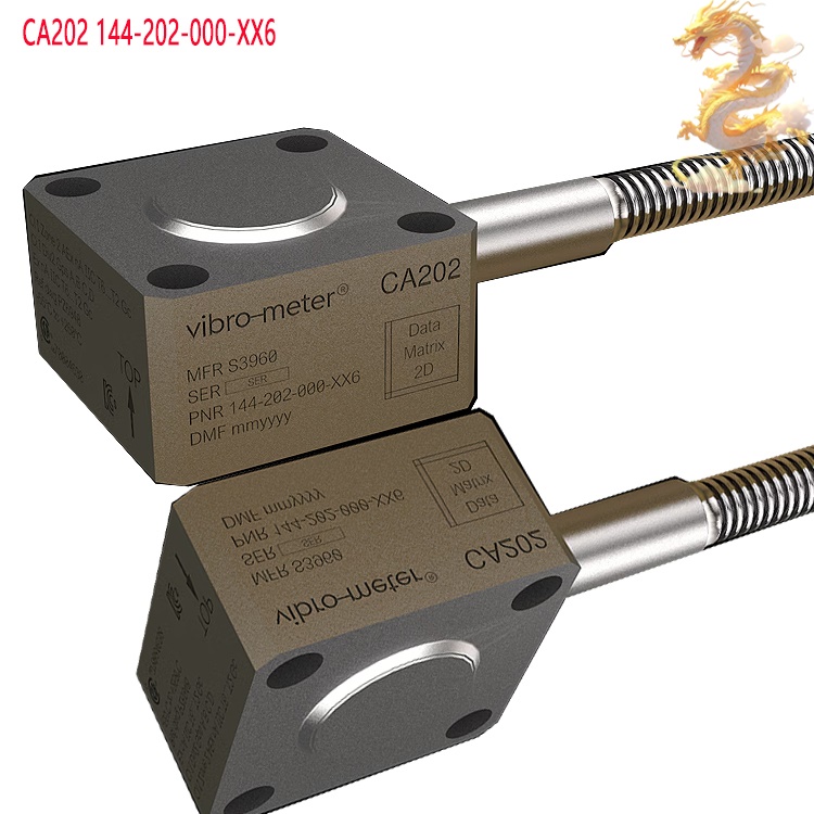
Signal Output: The sensor transmits this charge signal via a high-insulation, low-noise cable to an external charge amplifier or signal conditioner (such as the IPC704). This unit converts the signal into a standard voltage or current output, which can then be analyzed by a data acquisition system.
Key
Characteristic Note: Piezoelectric sensors are designed exclusively for
measuring dynamic pressures (fluctuating pressures, shock waves, or sound
waves); they cannot be used to measure static or quasi-static (constant)
pressures.
II. Core Advantages
The 143-231-000-011 series stands out in the highly competitive industrial sensor market, thanks to its exceptional resilience in extreme environments:
Extreme High-Temperature Tolerance: Utilizing specialized high-temperature piezoelectric materials, these sensors can operate stably over long periods in extreme heat—reaching temperatures as high as 650°C to 700°C (depending on the specific model, such as the CP232, CP234, etc.)—without the need for external water cooling.
Ultra-Wide Frequency Response: Featuring a very high natural frequency, the sensors can precisely capture high-frequency pressure pulsations and acoustic resonances, ranging from a few hertz (Hz) to tens of kilohertz (kHz).
High Insulation and Low Noise: Designed with a hermetically sealed, all-welded dual-shell structure, the sensors offer excellent electromagnetic compatibility (EMC) and exceptionally high insulation resistance, effectively isolating the system from interference caused by eddy currents and ground loops.
High
Reliability and Long Service Life: Engineered for "install-and-forget,"
long-term, maintenance-free operation, these sensors boast an extremely high
Mean Time Between Failures (MTBF), perfectly aligning with the operational
lifecycles of industrial equipment.
III. Industry Impacts
The 143-231-000-011 sensor serves as an essential "sentry" in the protection of industrial assets and the optimization of operational efficiency:
[ Real-time Sensor Monitoring ] ➔ [ Detection of Gas Turbine "Humming"/Anomalous Waveforms ] ➔ [ Triggering of Active Control/System Shutdown ] ➔ [ Prevention of Catastrophic Failures ]
1. Aerospace and Heavy-Duty Gas Turbines (Heavy Industry/Power Generation)
Eliminating Gas Turbine "Humming": In Dry Low-Emission (DLE) combustion chambers, thermodynamic instabilities can trigger high-frequency acoustic resonance—known as "humming." The 143-231-000-011 monitors combustion chamber pulsations in real time, preventing high-intensity pressure waves from shattering combustion liners or turbine blades.
Enhancing Combustion Efficiency: Assists in optimizing the fuel-to-air mixture ratio, ensuring combustion stability while simultaneously reducing NOx emissions.
2. Nuclear Power and Petrochemicals
Circuit and Pipeline Safety: Monitors flow-induced vibration (FIV) and water hammer effects within nuclear reactor coolant loops and high-pressure steam piping, preventing fatigue-related pipe ruptures.

High-Pressure Compressor Monitoring: Detects valve malfunctions and flow surges within reciprocating or centrifugal compressors in real time.
IV.
Operating Methods
To ensure measurement accuracy and maximize product lifespan, the following standardized installation and operating procedures must be followed:
Step 1: Inspection of Mechanical Components and Mounting Ports
Examine the threaded mounting ports on the equipment wall to ensure the threads are free of scratches, carbon deposits, and foreign debris. Ensure that the mounting surface is perpendicular to the thread in accordance with standards (a lack of perpendicularity can subject the sensor to shear forces, compromising measurement accuracy or even damaging the crystal).
Step 2: Washer and Sensor Installation
Always use the integrated metal sealing washer provided by the original manufacturer; never reuse an old washer.
Apply an appropriate amount of high-temperature anti-seize compound (such as a specified nickel-based anti-seize) to the sensor threads, taking care to ensure that no compound comes into contact with the sensing diaphragm at the tip of the sensor.
Step 3: Tightening with a Torque Wrench
Use a dedicated torque wrench to screw the sensor into the mounting hole.
Tighten the sensor strictly according to the torque specifications provided in the official technical manual. Insufficient torque may lead to gas leaks or signal distortion, while excessive torque can cause deformation of the sensor housing or disrupt the preload on the crystal.
Step 4: Electrical Connections and Cabling
Connect the low-noise charge cable (e.g., the segment between the housing and the preamplifier). Ensure that all connectors are clean and dry, and tighten the circular connectors to the specified torque.
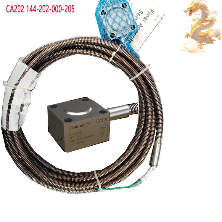
When routing cables, avoid placing them in direct contact with areas of extreme heat, and ensure an adequate bending radius (to prevent the internal shielding layer from breaking due to sharp bends).
V.
Crucial Precautions
Strictly Prohibited: Measuring Static Pressure – Do not use the 143-231-000-011 to measure constant (static) system pressure, as this will result in a lack of signal output or a slow drift in the charge signal.
Prevent Overheating and Thermal Shock – Although the sensor is designed for high-temperature environments, sudden, severe thermal shock (such as direct exposure to a fluid with a drastically different temperature) may cause the internal ceramic components or the crystal to crack. Maintain absolute cleanliness of the connectors: Piezoelectric sensors output weak charge signals (on the order of pC). Even the slightest trace of oil, moisture, or dust entering the connector plug can cause a significant drop in insulation resistance, leading to signal drift, increased noise, or output saturation. Use only designated electronic-grade anhydrous ethanol for cleaning.
Cable protection and securing: If a cable moves or vibrates during operation, the "triboelectric effect" can generate spurious charges that interfere with the signal. Therefore, the sensor output cable must be firmly secured to a support structure using cable clamps.
Recommended
products:
CP21X
143-216-000-111
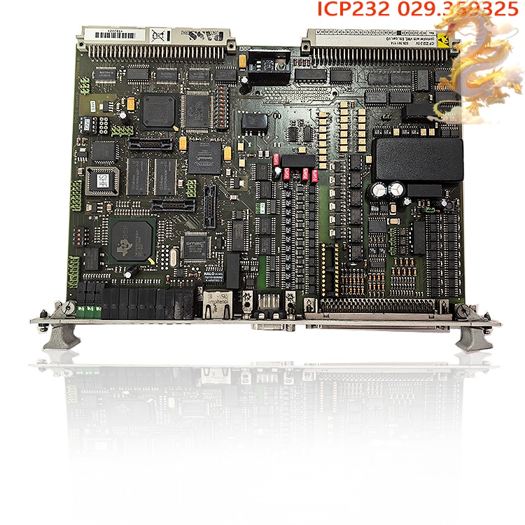
ICP232.2-5V
029.361114
ALSTOM
SPU232.2-5
ALSTOM
SPU232.2-CAN
SPU232.1-CAN
029.354 630
ALSTOM
SPU232.1-CAN
303088G-TRX32
CP21X
143-216-000-351
CP21X
143-216-000-251
CP21X
143-216-000-161
CP21X
143-216-000-151
CP21X
143-216-000-141
CP21X
143-216-000-131
CP21X
143-216-000-121
More......
PRODUCT TAGS
RELATED PRODUCTS
PLC Dragon Automation
Address: Wanda Plaza, Chengdu, Sichuan Province
Google email: wkcarshop666888@gmail.com
Industrial Control Sales Consultant: Amelia
Whatsapp: +86 18030295882