Mir based on STM32MP135 development board bare metal development application notes, MCU friendly transition MPU
Date: Apr 02, 2024Views:
Previously, microprocessors (MPUs) and microcontrollers (MCUs) were two completely different devices. MPUs supported rich software systems such as Linux and related software stacks, while MCUs typically focused on bare metal and RTOS. In recent years, with the increasing performance of MCU, the difference between MCU and MPU has become increasingly blurred.
STM32MP135 is an entry-level, cost-effective MPU suitable for scenarios where MCU performance does not meet requirements or requires running Linux. Mir's STM32MP135 development board provides software for Bare metal bare metal development based on STM32Cube, which can further enhance real-time performance support to meet the needs of users for implementing hard real-time applications. This is particularly user-friendly for users who are accustomed to using MCU for development, as it allows developers to have a development experience similar to MCU while utilizing the powerful performance of MPUs. Mill provides support for bare metal development environments. Next, let's introduce how to conduct bare metal development on Mill's STM32MP135 development board.
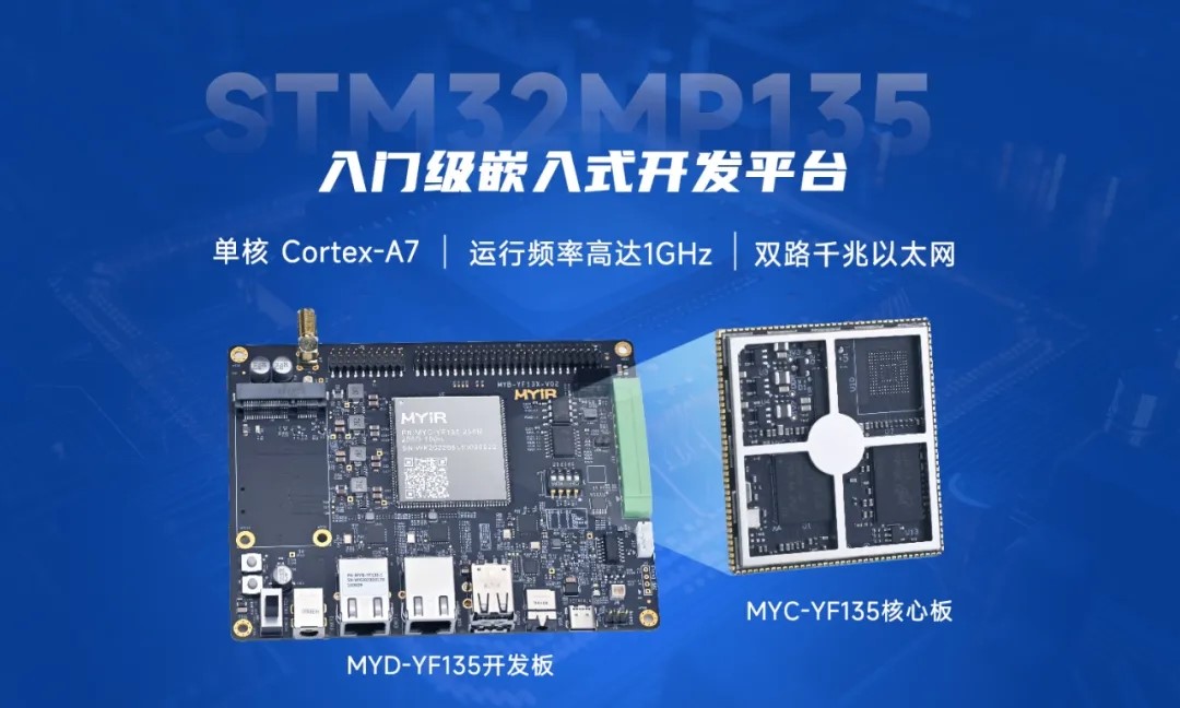
Mir is based on the STM32MP135 core board and development board
1. Environmental setup
1.1 Obtain source code
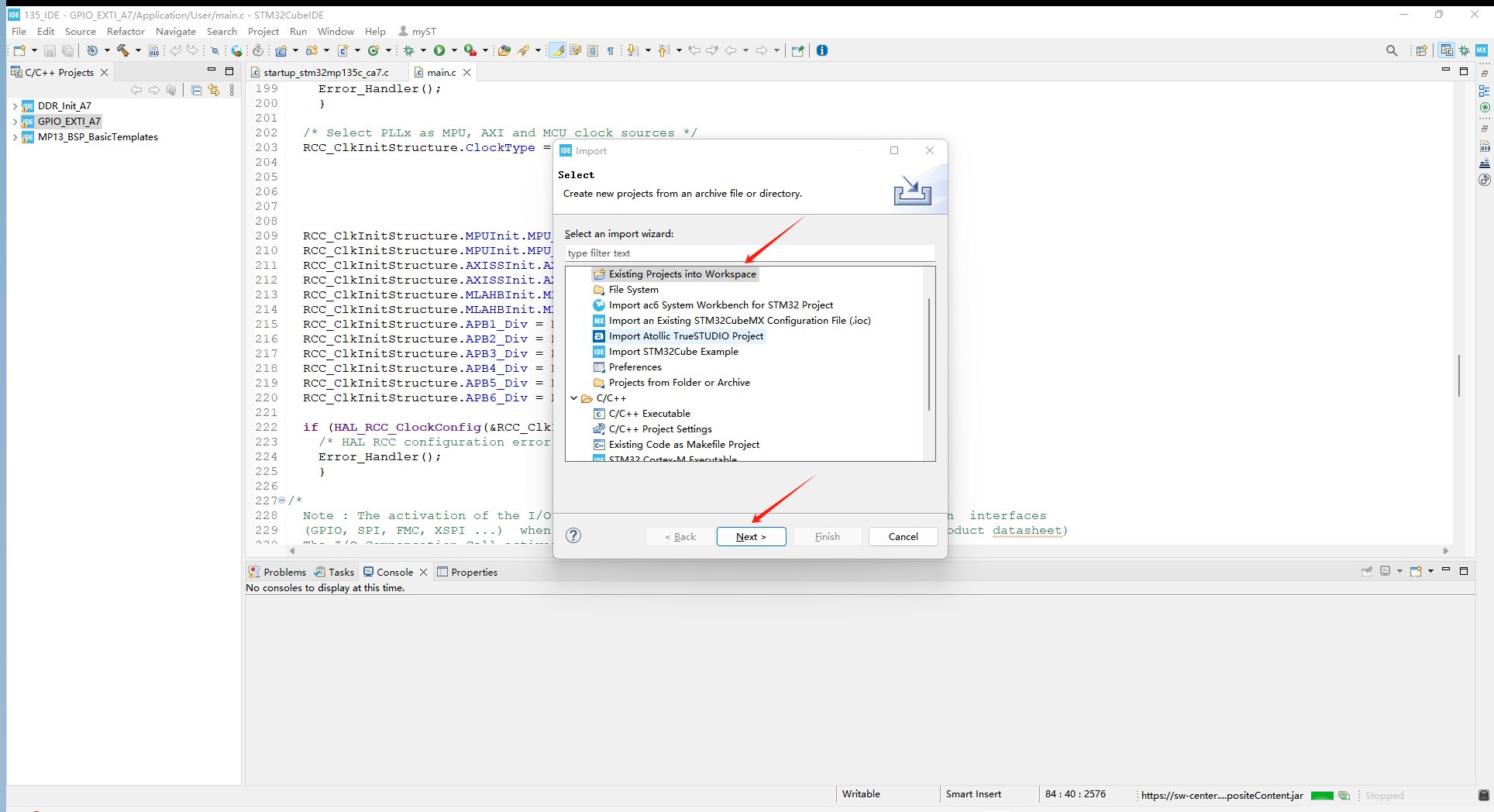
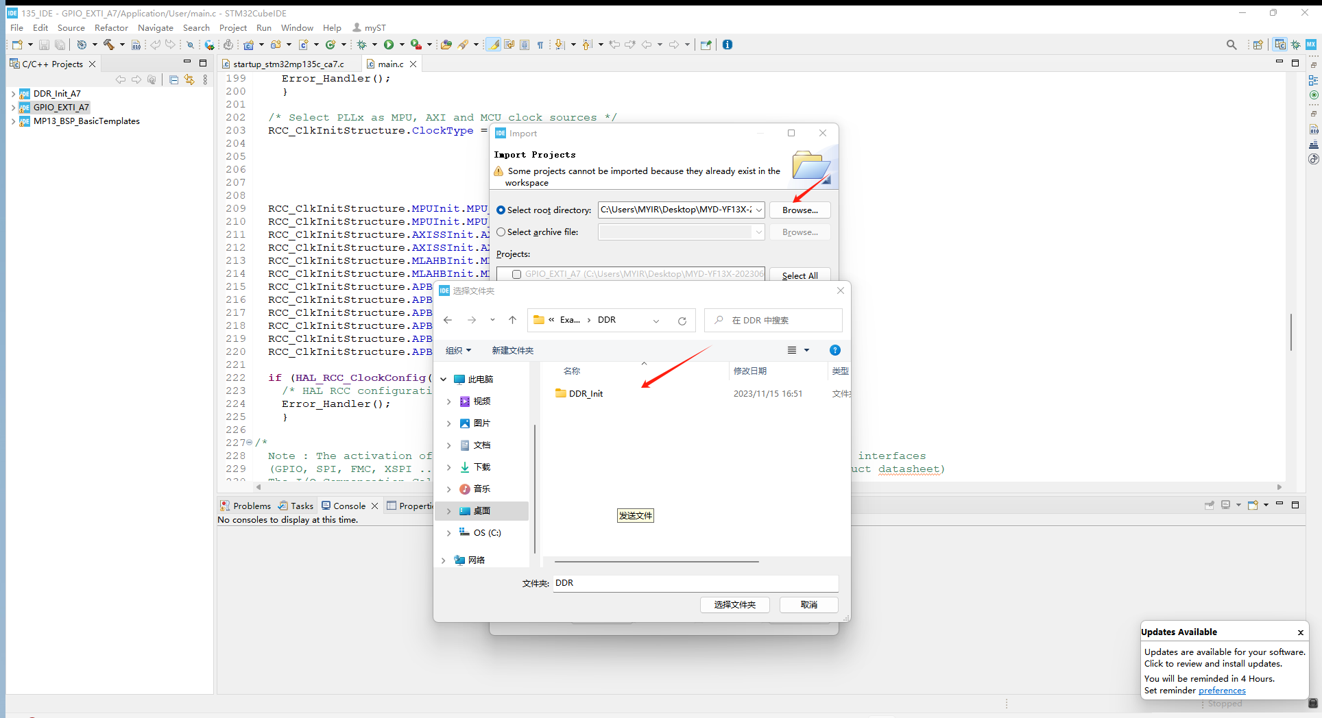
Download the 04_Sources/STM32CubeMP13-1.0.0 source code package provided by Mill, and use STM32CubeIDE to import the STM32Cube.FW-MP13_V1.0.0 \ Projects \ STM32MP135C-DK \ Examples \ DDR \ DDR-Init file. Click File ->Import ->Existing Projects into workspace.
1.2 Compile source code
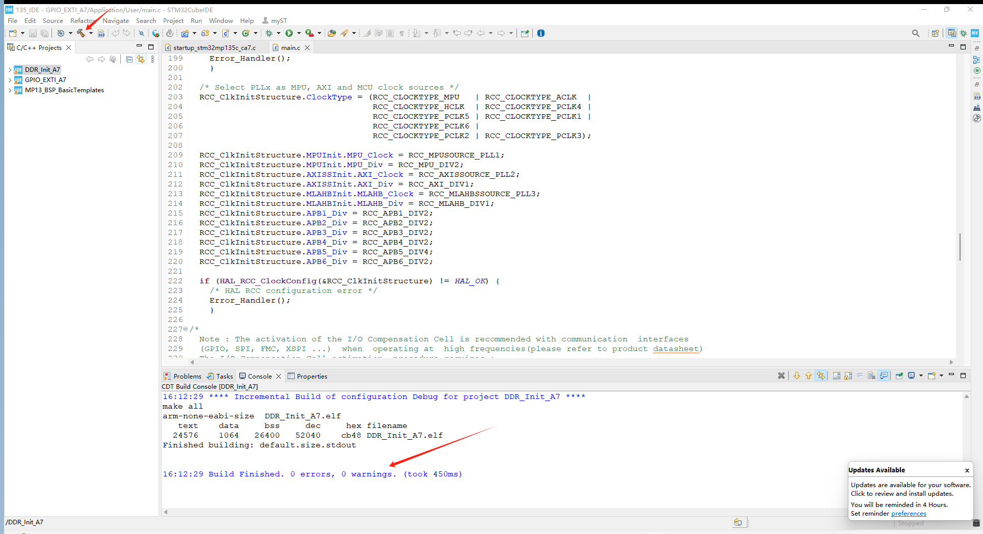
After successfully importing the project, compile it and click on it. When 0 errors appear below, 0 warnings indicate successful compilation.
1.3 Development board wiring
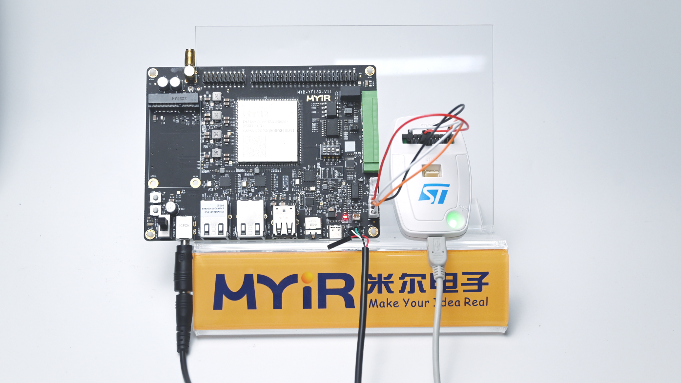
After the engineering source code is compiled, the development board needs to connect to ST Link for debugging, and set the dial switch to engineering mode 1-4:1000. The interface used is J7. Since the pins are not soldered at the factory, users need to solder them themselves. The wiring method is shown in the following figure:
1.4 Debugging engineering
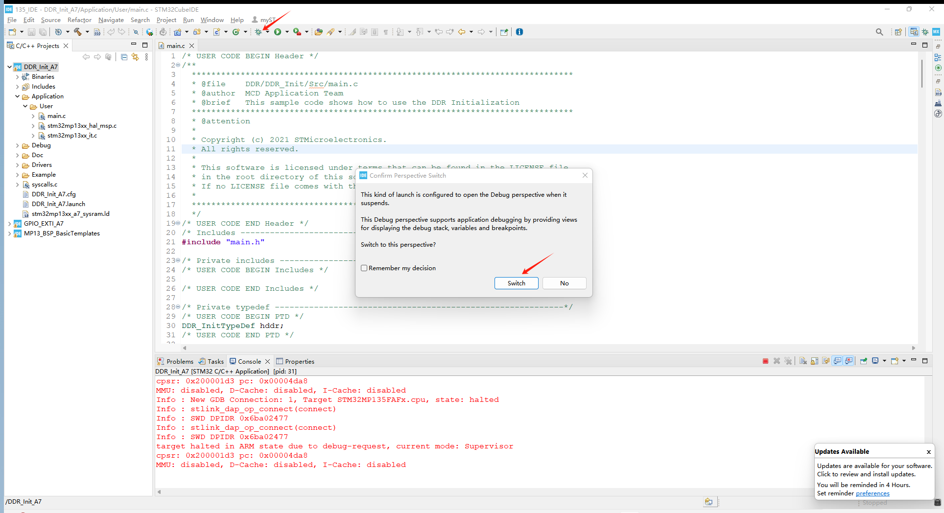
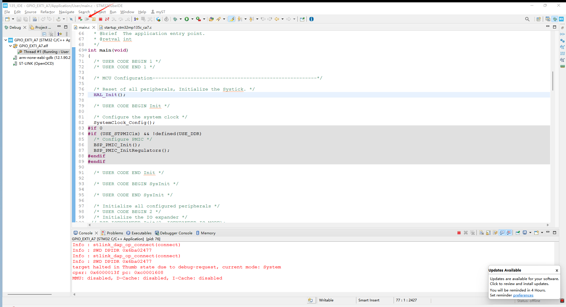
After compiling in 2.3, proceed with the debugging operation and click on debug, as shown in the figure:
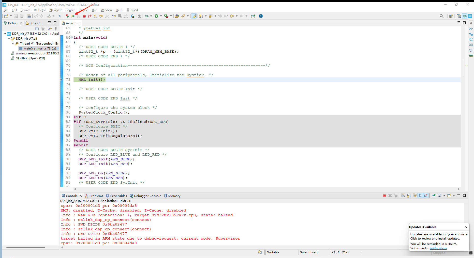
After entering the interface, click on Run at Full Speed and see the blue light on the development board flashing, indicating successful DDR initialization:
2. Application loading
2.1 Application environment configuration
After initializing the DDR, the next step is to let the application run on it. Here, we choose the engineering application under the MYD-YF13X-20230601 \ STM32CubeMP13-1.0.0 \ Projects \ STM32MP135C-DK \ Templates \ BSP_BasicTemplates path:
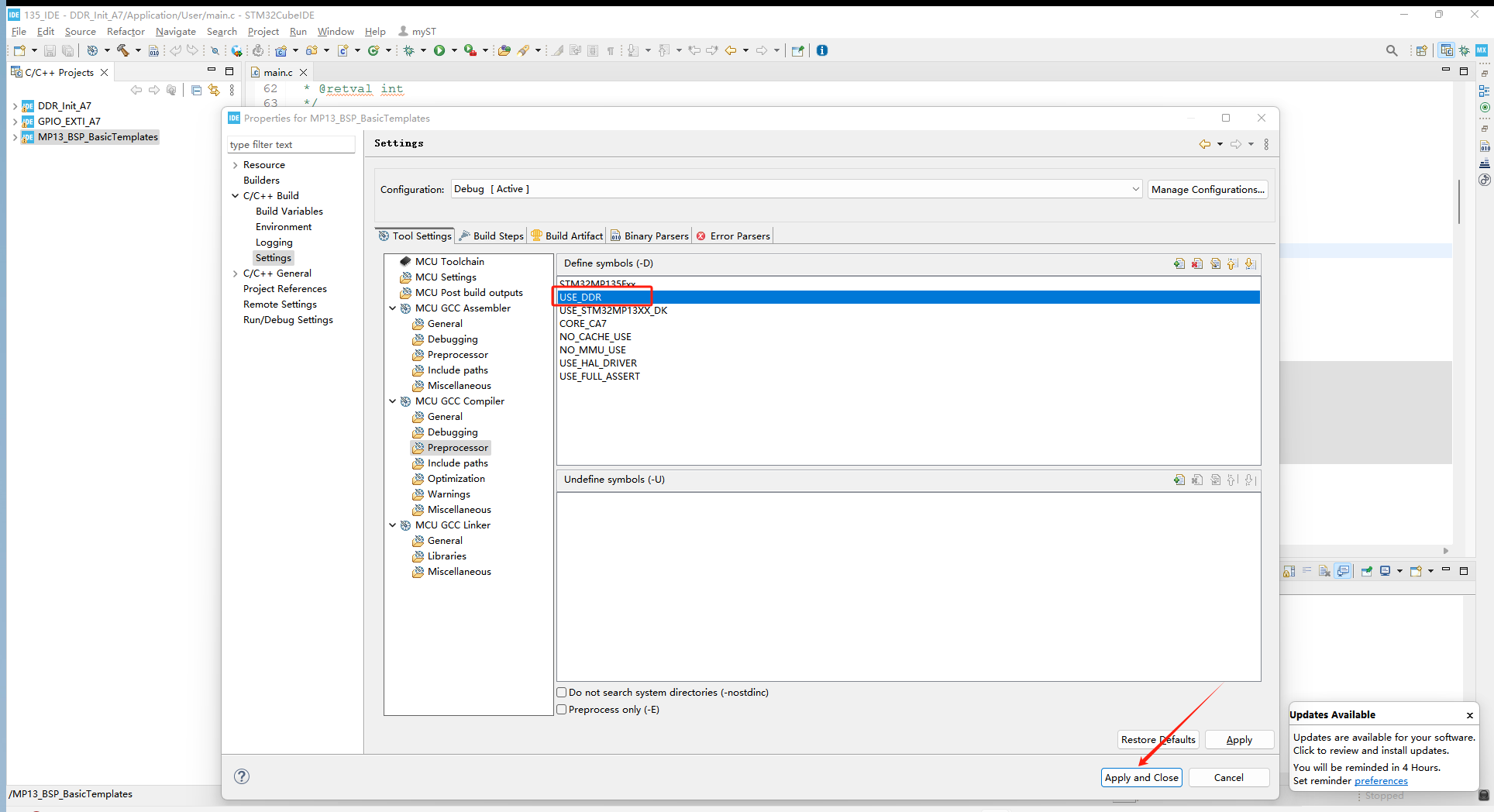
Import the project according to the method in 1.1. After seeing that the project has been successfully imported, right-click on the project file name and then click on Properties:
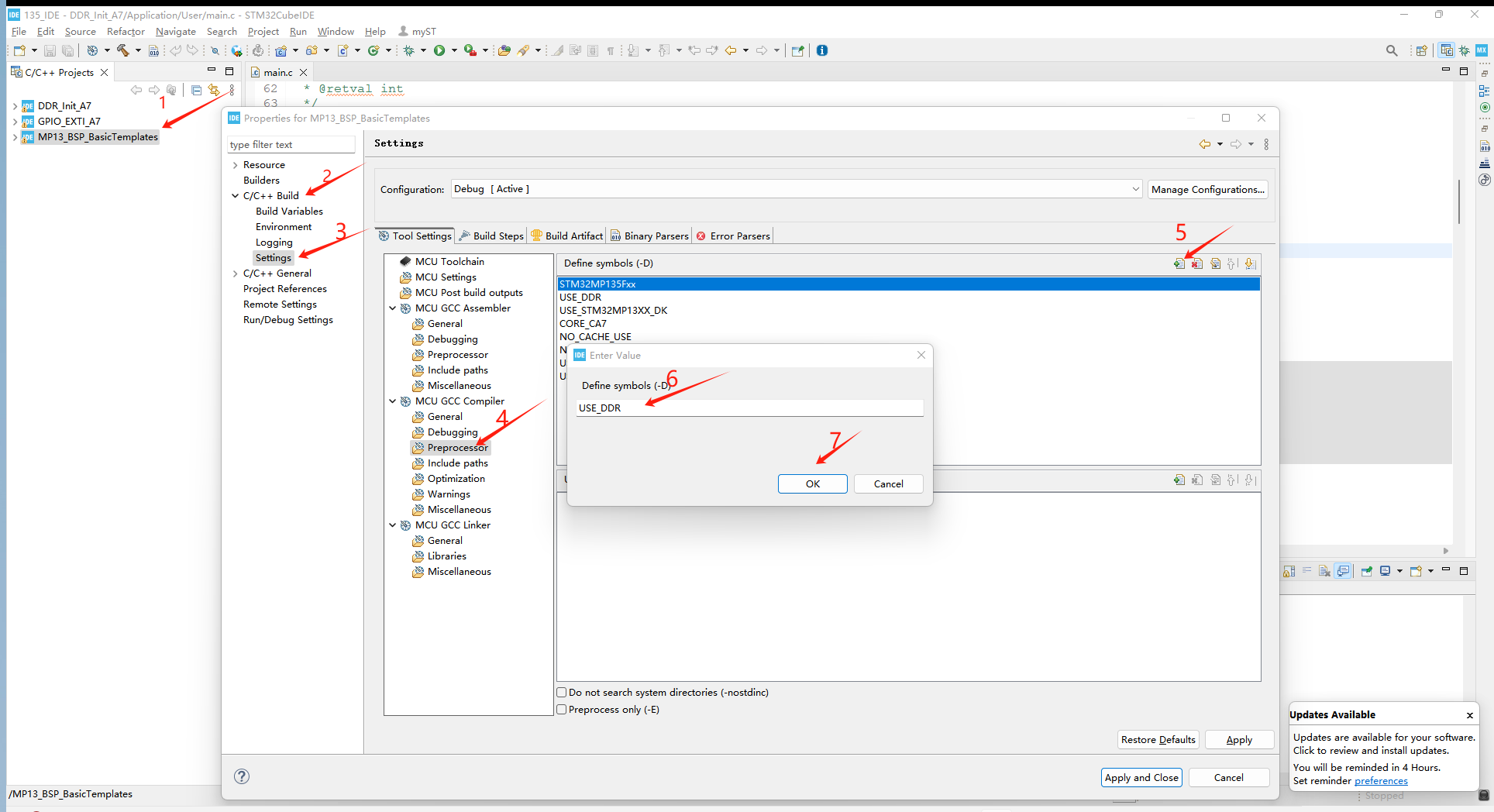
After performing the above operations, pop up the Enter Value and add the USE.DDR character and save it:
Continue to right-click on the project file name and then click on properties:
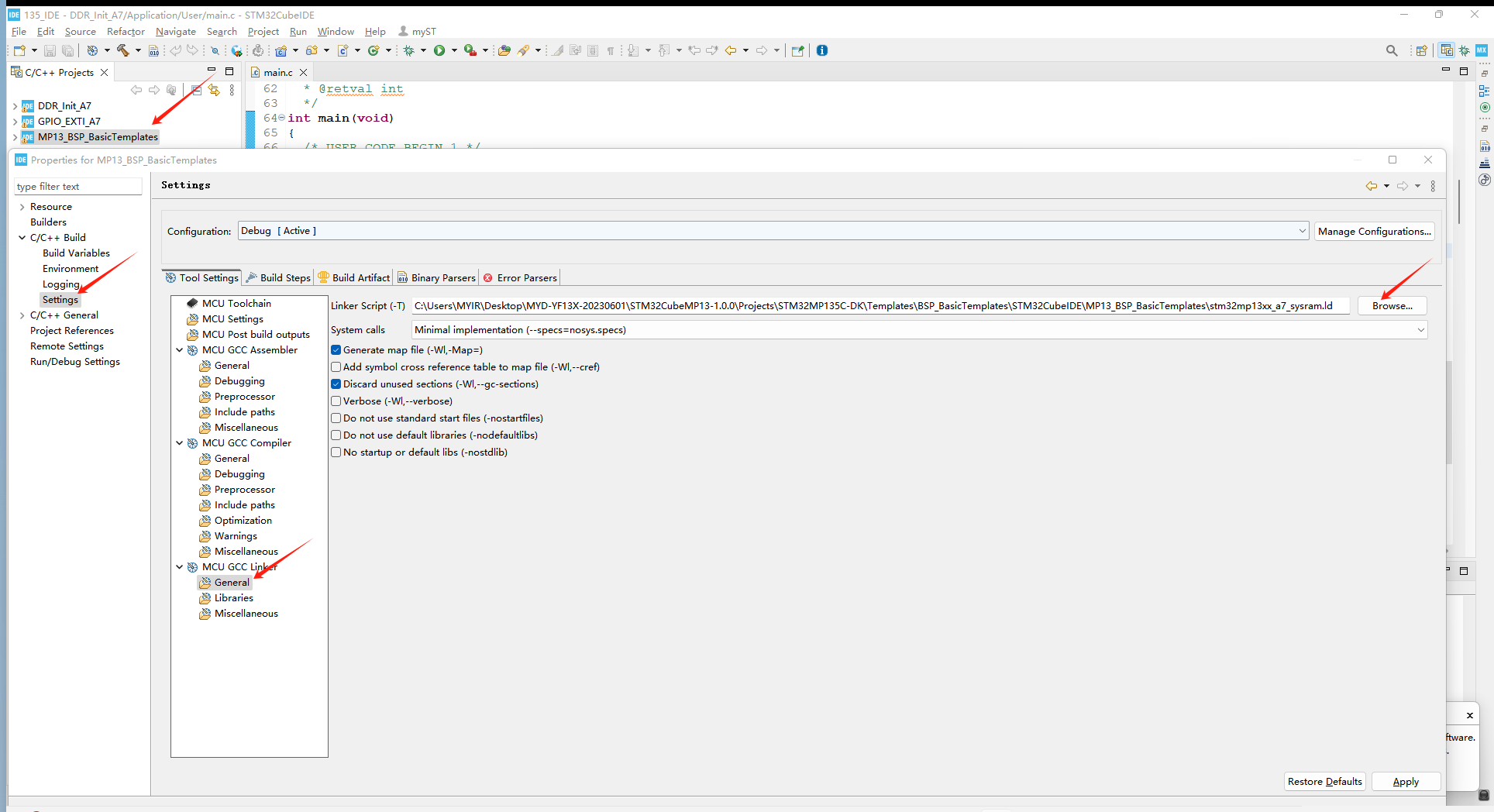
Follow the steps above to open the stm32cubeMP13-1.0.0 \ Projects \ STM32MP135C-DK \ Templates \ BSP_BasicTemplates \ STM32CubeIDE \ MP13_BSP_BasicTemplates path to the stm32mp13xx-a7_sysram.ld file: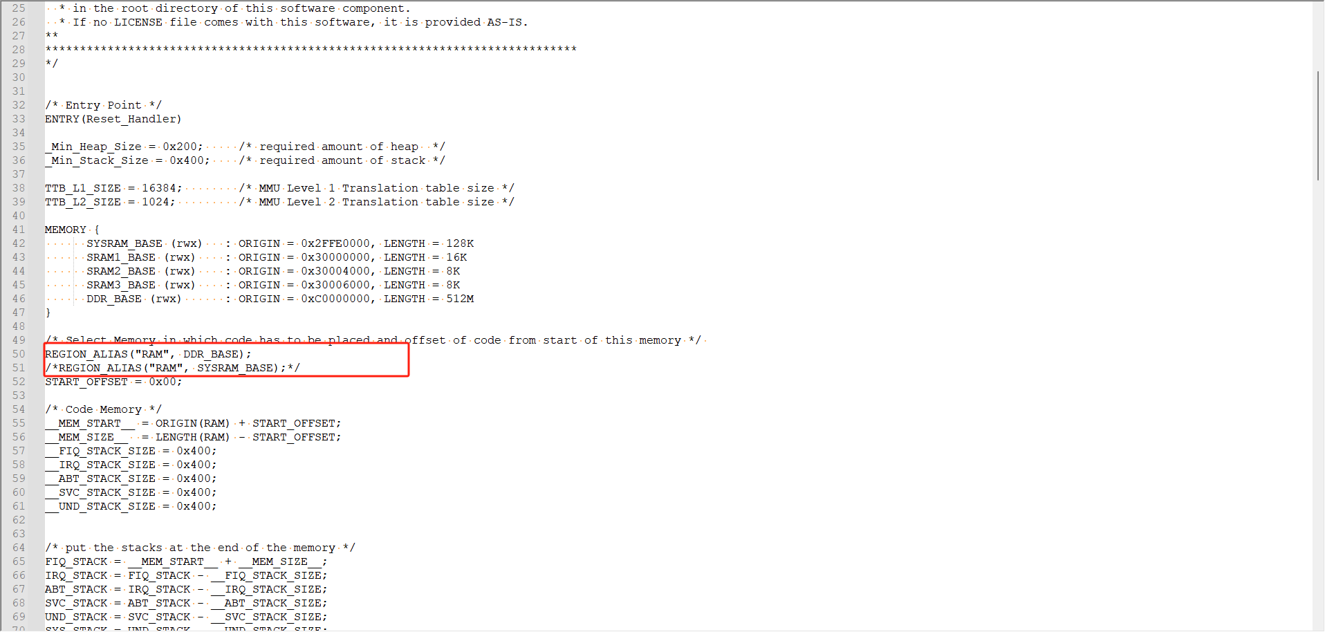
Revision-ALIAS ("RAM", DDR-BASE); Delete some of the comments, then comment out REGION-ALIAS ("RAM", SYSRAM-BASE), save and select:
2.2 Debugging applications
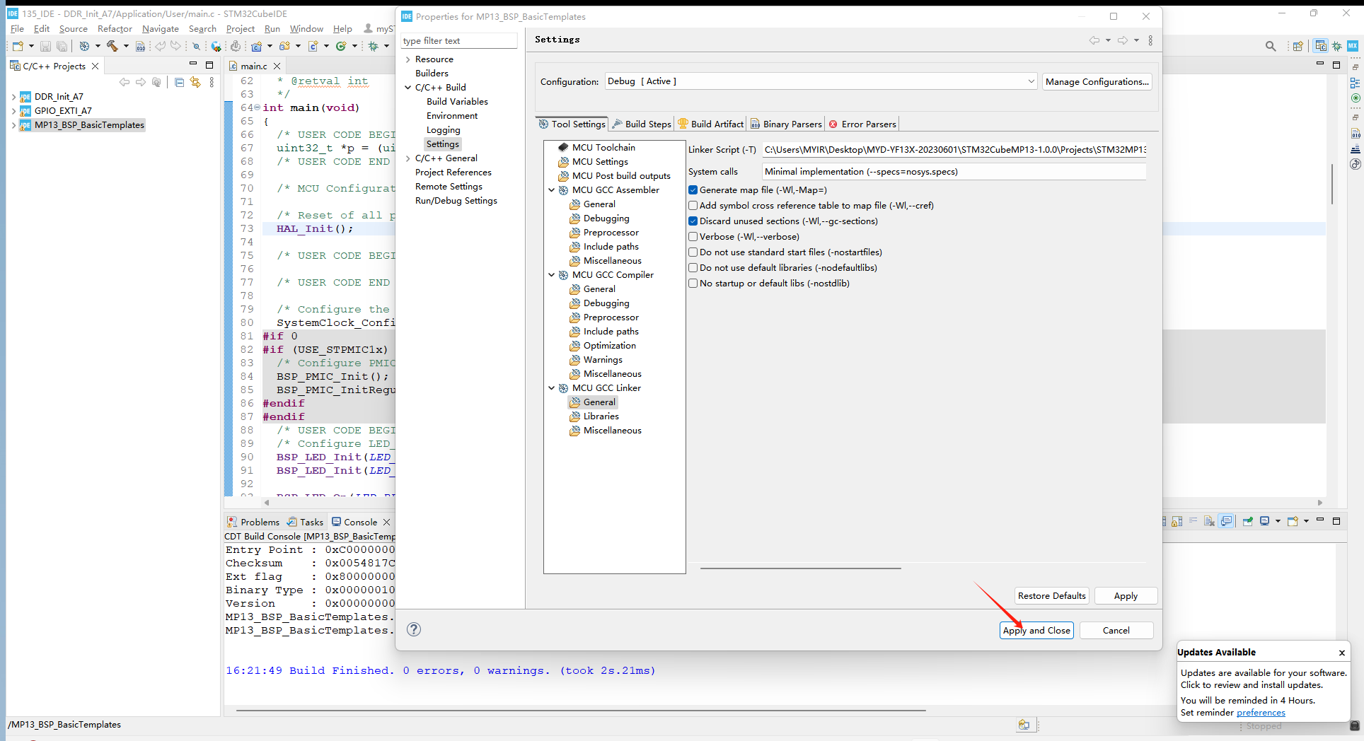
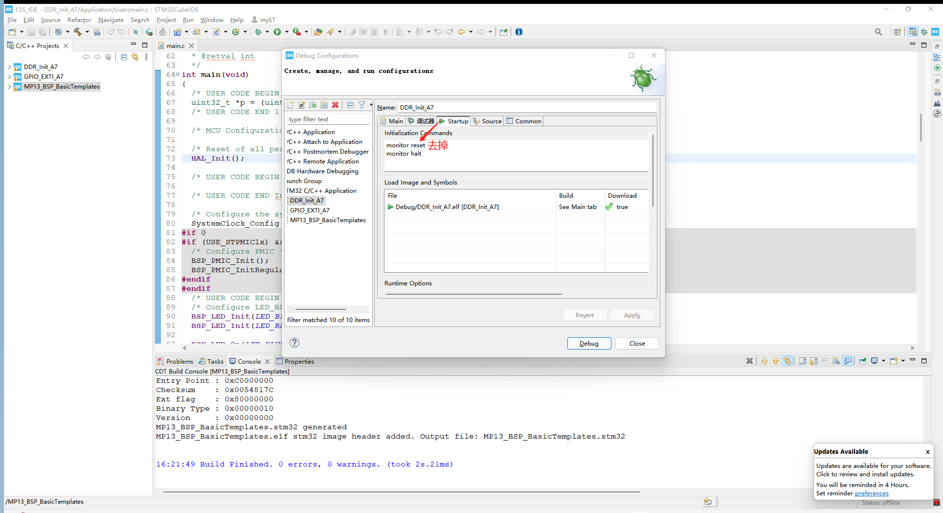
After configuring the above environment, it is also necessary to perform a configuration during the application debugging phase. Open the debugging settings interface of the project, click start, delete the monitor reset, save and debug:
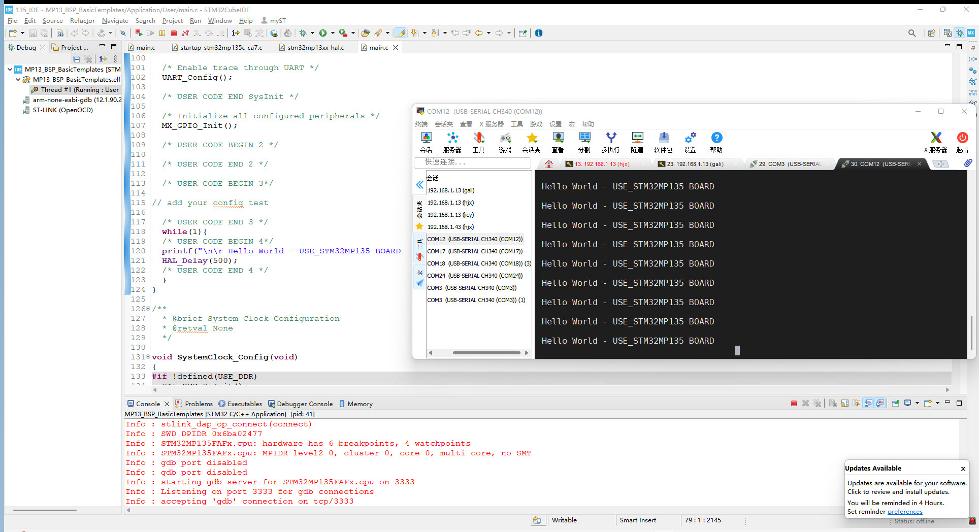
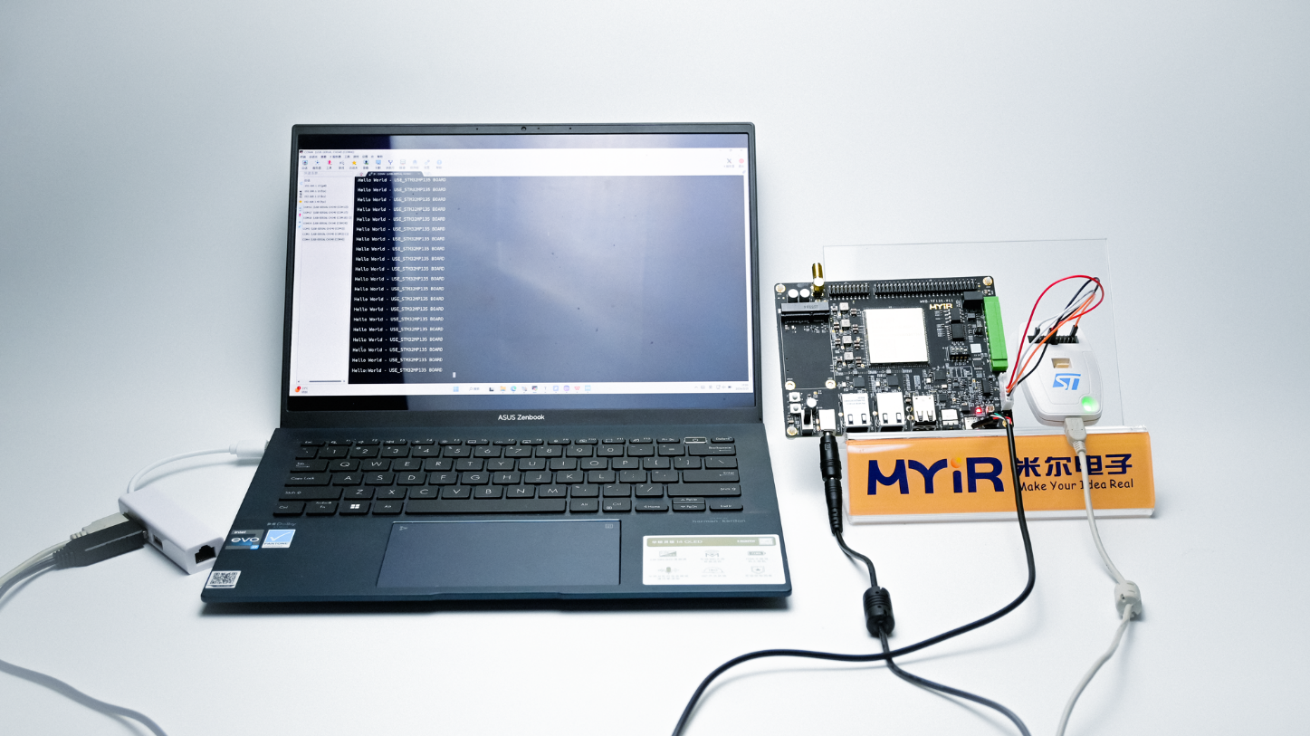
Connect the development board to the serial port, run at full speed, and the serial port will print Hello World - USE-STM32MP135 BOARD. At this point, the application debugging is successful.
3. Create an application
3.1 Adapt to hardware
Taking the heartbeat light on the Miller MYD-YF13x development board as an example, the first step is to determine the GPIO port used by the heartbeat light. Looking at the hardware schematic, it can be seen that the heartbeat light is connected to SPI5-MOSI:
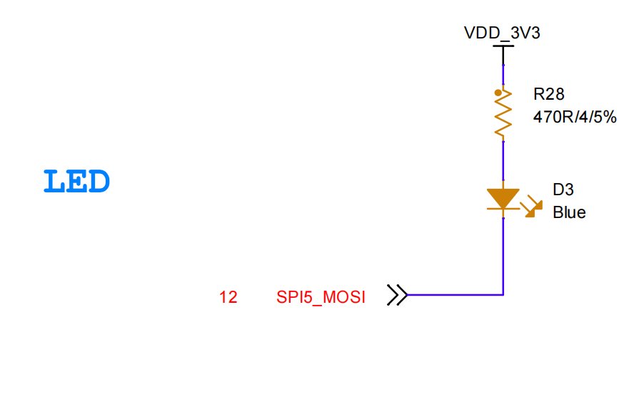
By checking Mill's Pin List, it can be inferred that the corresponding pin for SPI5-MOSI is PH12. Therefore, the next step is to create a project to configure the flashing of the heartbeat light.
3.2 Engineering creation
The project created by Mill is located in the path STM32CubeMP13-1.0.0 \ Projects \ STM32MP135C-DK \ Examples \ GPIO \ GPIO-EXTI. Import the project according to the method in 1.1, as follows:

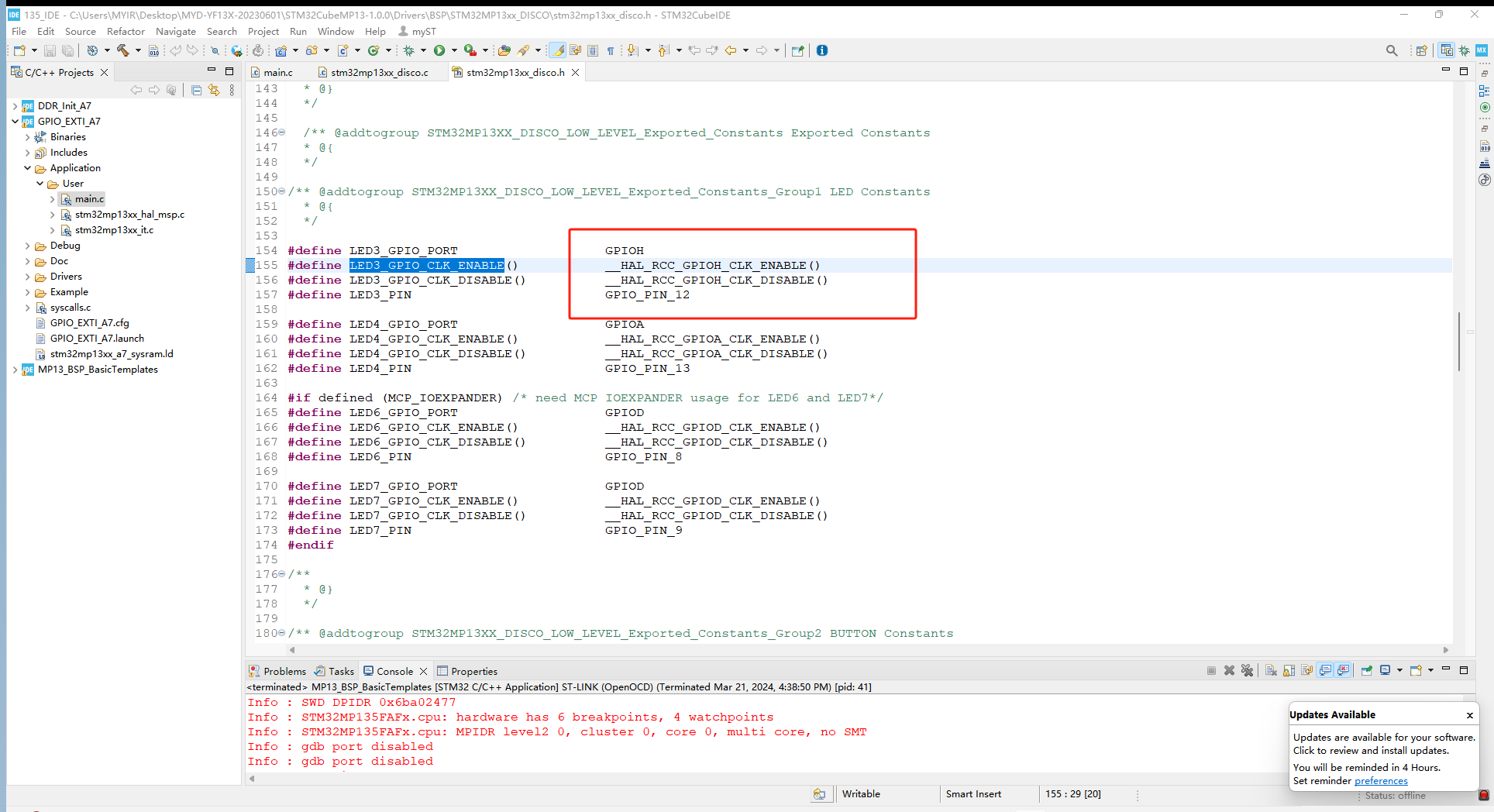
Start configuring the heartbeat light and modify the heartbeat light pin configuration in stm32mp13xx_disco. h:
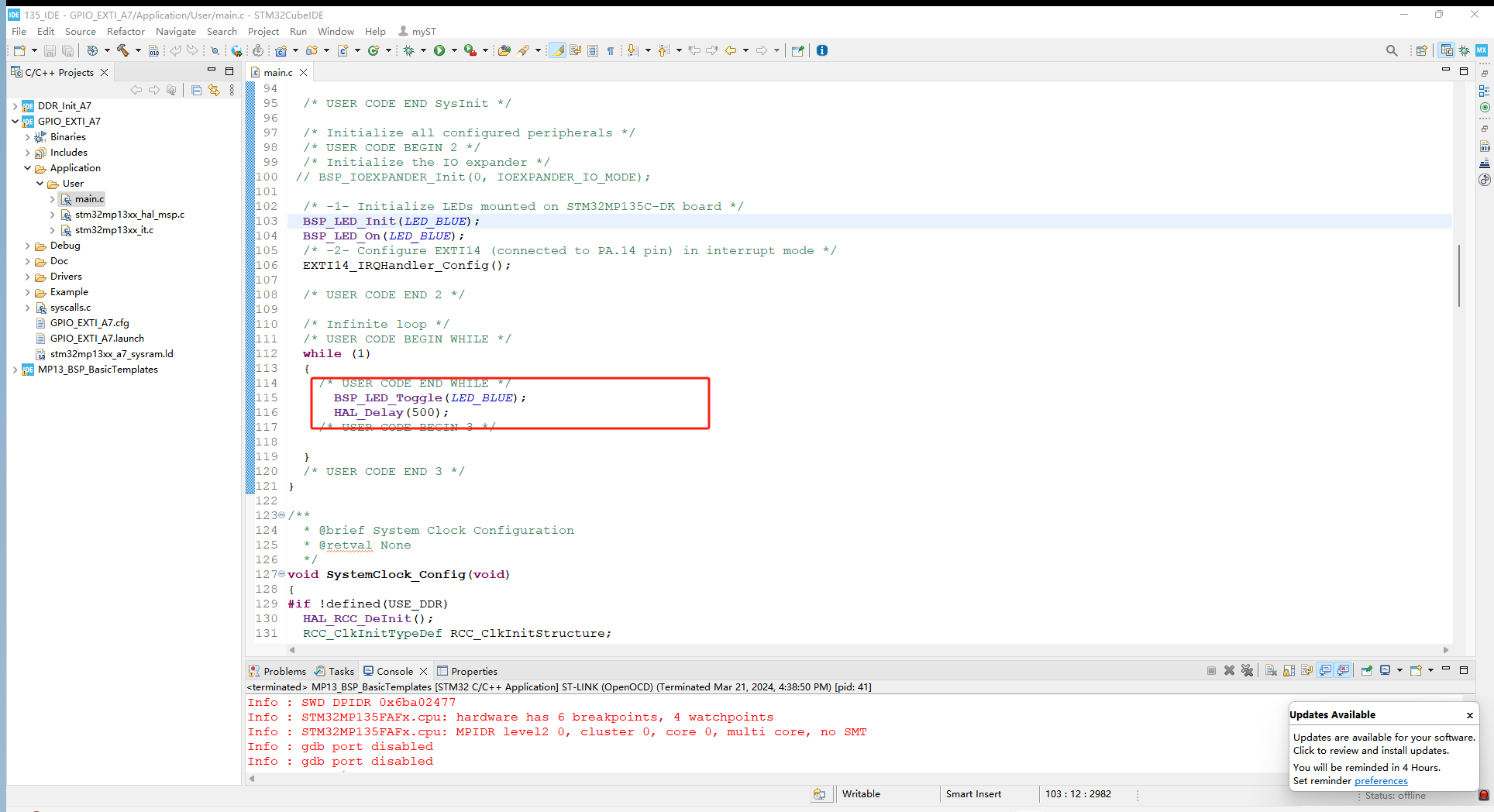
After making the modifications, go back to the main. c file and add the code for the heartbeat light in the while function:
After compilation and debugging, let the program run at full speed and you can see the blue light flashing on the development board:
The created project has been successfully debugged.
Product Introduction
The Miller STM32MP135 development board is based on the STM32MP13 series processor, with a single core Cortex-A7 design and a running frequency of up to 1GHz. It is designed specifically for entry-level Linux, bare metal, or RTOS systems. The development board adopts 12V/2A DC power supply, equipped with 2 Gigabit Ethernet interfaces, 1 USB 2.0 protocol MINI PCIE socket 4G module interface, 1 RGB display interface, 1 audio input/output interface, 2 USB HOST Type A, 1 USB OTG Type-C interface, 1 Micro SD interface, etc. The development board has rich interfaces and is suitable for scenarios such as energy and power, industrial control, industrial gateway, and industrial HMI.

Warehouse product recommendation:
PFXA401F 3BSE024388R3
PFXA401S 3BSE024388R2
PFCA401S 3BSE024387R2
PFCA401F 3BSE024387R3
More......
RELATED NEWS
PLC Dragon Automation
Address: Wanda Plaza, Chengdu, Sichuan Province
Google email: wkcarshop666888@gmail.com
Industrial Control Sales Consultant: Amelia
Whatsapp: +86 18030295882
12A3256BC9DA41BAB264DB676273DA32.png)


3BE7E049824E4F11BE61AD65D86DFEBD.png)