How to establish communication between PM866K01 3BSE050198R1 redundant controllers?
Date: Oct 18, 2025Views:
PM866K01 3BSE050198R1 Redundant Controller Communication Establishment Guide
Core Communication Interfaces and Protocols
Redundant Module Configuration: Two PM866K01 modules are deployed as active and standby controllers, physically connected via PROFIBUS DP, Ethernet, or fiber optics. The fiber optic interface supports multimode (850nm/1310nm) and single-mode (1310nm/1550nm), with a transmission distance of up to 20km (single-mode). SC/FC/ST interface options are available, with an SC interface standard.

Power Redundancy: Dual redundant power inputs (DC 12-36V) are used, with reverse polarity protection and voltage isolation, ensuring seamless failover in the event of a power failure.
Synchronization: The active and standby controllers synchronize their states via a heartbeat line or synchronization protocol (such as IEEE 802.3 Ethernet). In the event of a failure, failover automatically occurs to the standby controller, with a failover time of less than 1ms, ensuring continuous system operation.
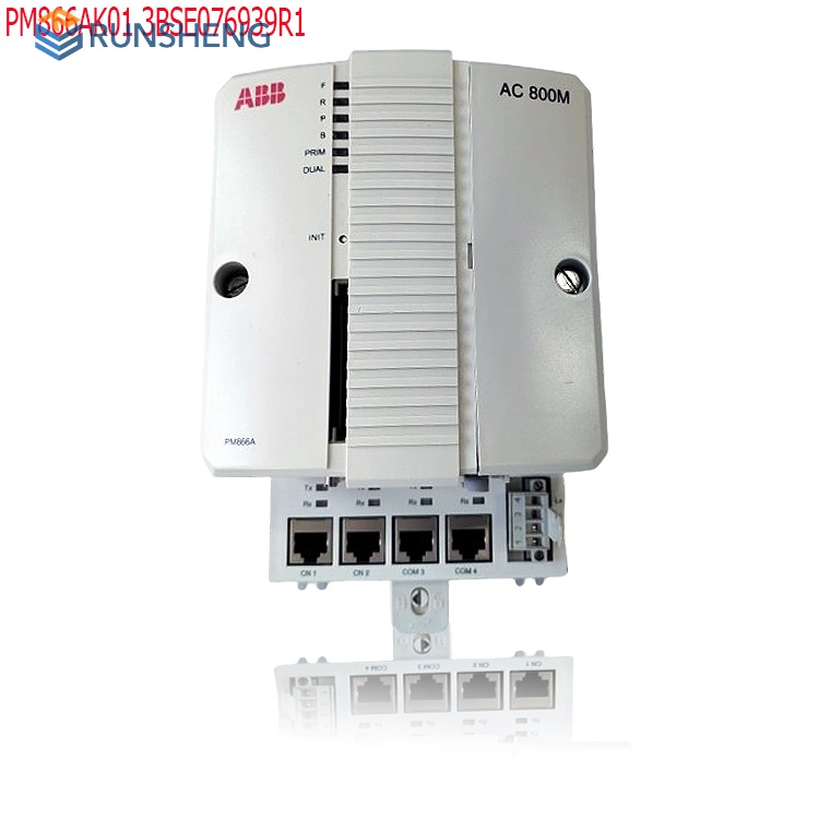
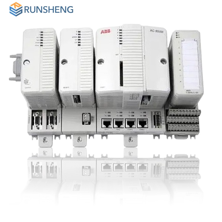
Hardware Interfaces: Integrated dual redundant Ethernet ports (RJ45), RS485 serial port, USB 3.0, and CAN bus interfaces, all with hot-swappable functionality.
Protocol Support: Compatible with industry-standard protocols such as EtherNet/IP, Modbus TCP/IP, Profinet, OPC UA, and Profibus DP, seamlessly integrating with third-party devices from Siemens, Schneider, and other manufacturers, as well as HMI/SCADA systems (such as WinCC, Intouch, and KingView).
Redundancy: Utilizing a 1:1 hot standby architecture, the controller switches between active and standby controllers in ≤10ms, with no data loss during the switchover process. A built-in fault self-diagnosis module supports SIL 2 safety certification.
.jpg)
Software Configuration and Protocol Settings
Programming Tools: Use ABB's Control Builder M software for programming and configuration, enabling redundancy modules and defining active and standby controller role assignments and failover logic.
Communication Protocols: Supports a variety of industrial protocols, including:
Modbus TCP: For communication with HMIs, SCADA systems, or third-party devices (such as Siemens PLCs).
OPC UA: Enables data exchange with host software (such as WinCC and Intouch), supporting remote monitoring and diagnostics.
PROFIBUS DP: Connects field devices (such as I/O modules and sensors) and supports high-speed data acquisition and control.
Ethernet/IP: Used for inter-controller communication and engineering station connection, with built-in dual Ethernet ports (RJ45) and network redundancy.
Network Parameter Configuration: Set network parameters such as the IP address, subnet mask, and gateway in the software to ensure the controller is accessible within the LAN. For example, the default IP address is 192.168.1.1, which can be modified through the web interface or the software.
Network and System Integration
Data Interaction:
Connects to HMI/SCADA systems (such as WinCC and Intouch) via the OPC UA protocol, or integrates with domestic configuration software (such as KingView) via Modbus TCP.
Supports IEEE 1588 PTPv2 time synchronization (accuracy of ±1μs), ensuring precise multi-device coordinated control.
Fault Diagnosis: Built-in self-diagnostic functions monitor the status of the CPU, memory, and communication interfaces in real time, outputting fault codes (such as "E102" for a memory error) and notifying maintenance personnel via an alarm system.
.jpg)
Safety and Diagnostic Configuration
Safety Level: Supports SIL 2 certification, with built-in fault diagnostics and emergency shutdown mechanisms to ensure personnel and equipment safety.
Status Monitoring: LED indicators (RUN/ERR/COM) display real-time operating status, and the software interface allows viewing CPU load rate, communication status, and error codes.
Remote Access: A built-in web server supports remote access to controller status via a browser for real-time monitoring and parameter adjustment.
Hardware Configuration and Connection Steps
Hardware Preparation:
One master and one standby PM866K01 controller, along with a redundant power supply module (such as the SD822), a redundant communication module (CI854/CI871), and a redundant synchronization cable (3BSE013195R1).
Redundant switches or ring switches ensure the network topology has no single point of failure.
I/O modules (such as the TB805/TB806) and an expansion bus (CEX bus) module (BC810K02).
Physical Connections:
The master and standby controllers are interconnected via redundant Ethernet ports or PROFIBUS DP, with synchronization cables connected to the redundant ports on the controller backplanes.
Redundant power supply modules are connected in parallel via the DC bus to ensure power supply redundancy.
I/O modules are expandable via the CEX bus, supporting up to 64 local modules and 256 remote I/O stations.
Software Configuration and Redundancy Enabling
Tools and Parameter Settings:
Use ABB Control Builder M software to configure the system and configure the controller IP address (e.g., 192.168.1.1/24), subnet mask, and redundancy parameters (master/slave priority, heartbeat interval).
Enable redundancy: Select "Redundancy Enabled" in "Controller Settings" and set the master/slave controller synchronization mode (e.g., fast synchronization or full synchronization).
Configure the communication protocol: Select EtherNet/IP or Modbus TCP based on the host computer's requirements, and set port mapping and data tags.
Network Diagnostics and Testing:
Test the network connectivity of the master and slave controllers using the ping command and use network diagnostic tools to check for IP conflicts or configuration errors.
Simulate fault scenarios (e.g., disconnecting the power to the master controller) to verify redundancy switchover functionality and data integrity.
Use the built-in web server (default IP: 192.168.1.1) to monitor real-time status or view CPU load and fault codes using "ControllerStatus." Integration Methods with Host Computers
HMI/SCADA Systems: Connect to software such as WinCC and Intouch via the OPC UA protocol, or connect to domestic platforms such as KingView and Kunlun Tongtai via Modbus TCP.
Industrial IoT: Connect to the Industrial IoT platform via the Ethernet interface for remote parameter adjustment and status monitoring.
Third-Party Devices: Connect to Siemens PLCs and Rockwell equipment via Profinet or EtherNet/IP protocols, or connect to sensors and actuators via serial ports.
Testing and Verification
Functional Testing: After configuration is complete, perform a primary/standby switchover test to verify that the backup controller can seamlessly take over in the event of a failure.
Communication Testing: Use network testing tools (such as ping or Modbus scanner) to verify normal communication with the host computer and field devices.
Performance Testing: Test the controller's response speed and stability through high-load scenarios to ensure it meets process requirements (such as 0.1mm welding accuracy and ±1°C temperature control).
Maintenance and Troubleshooting
Daily Maintenance: Regularly check the cooling fan, power module, and communication interface to ensure that the ambient temperature (-25°C to 60°C) and humidity (5%-95% non-condensing) meet requirements.
Troubleshooting:
Hardware Failure: Replace the faulty module (e.g., CPU, power supply) and use a battery-backed RAM to prevent program loss.
Communication Failure: Check cable connections, switch configuration, and protocol parameters, and use network diagnostic tools to locate the problem.
Software Failure: Use Control Builder M's online diagnostics to view error codes or use the watchdog timer to automatically restart.
Key Notes
Hardware Compatibility: Ensure that all connected devices (e.g., I/O modules, power modules) are compatible with the PM866K01 to avoid communication failures due to hardware mismatches.

Software Version: Use the Control Builder M software that matches the controller firmware version to avoid version conflicts.
Environmental Adaptability: The controller operates in a temperature range of -20°C to +60°C. For a wider temperature range (-40°C to +85°C), the PM866K01-EXT expansion model is available.
Physical Environment: Operating temperature -20°C to +60°C, vibration resistance 10g (10-500Hz), installation in a standard 3U rack, and protection against electromagnetic interference.
Power Requirements: DC 24V ±10%, typical power consumption 25W, redundant power supply modules and overvoltage/reverse polarity protection are required.
Maintenance: The controller does not support hot swapping. Power must be turned off and the program backed up when replacing. The program is stored in the eMMC and is not lost during power outages. Firmware upgrades only update the operating system.
Verification and Testing
Redundancy Test: Simulates a primary controller failure to verify that the backup controller automatically takes over (switchover time ≤ 10ms) and checks data integrity.
Communication Test: Use a network testing tool (such as Wireshark) to verify normal data packet transmission and correct protocol configuration.
Performance verification: Test the control cycle (10ms-1s), I/O processing capability (10,000 points of real-time processing) and computing performance (50 million instructions/second) when running at full load.
Related product recommendations:
PM858K02 3BSE082896R1
PM865AK01 3BSE031150R1
PM865K01 3BSE031151R1
PM802F 3BDH000002R1
PM803F 3BDH000530R1
PM820-1 3BSE010797R1
PM820-2 3BSE010798R1
PM825 3BSE010796R1
PM825-1 3BSE010800R1
PM858-C 3BSE093350R1
PM861AK01 3BSE018157R1
PM864AK01 3BSE018161R1
PM864AK01-eA 3BSE018161R2
PM861A 3BSE018162R1
PM866 3BSE050200R1
PM866AK02 3BSE008538R1
PM866-2 3BSE050201R1
PM866AK02 EXC3BSE076939R1
PM866K01 3BSE050198R1
PM891K02 3BSE053242R1
PM891K01 36BSE053241R1
PM891 3BSE053240R1
More...
RELATED NEWS
.jpg)


Shanxi Runsheng Import and Export Co., Ltd
Address: 3301, Building A, Wanda Center, No. 175 Jiefang Road, Xinghualing District, Taiyuan City, Shanxi Province
Google email: wkcarshop666888@gmail.com
Industrial Control Sales Consultant: Amelia
Whatsapp: +86 18030295882

