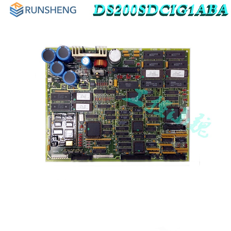
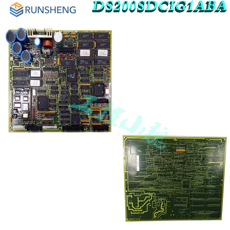
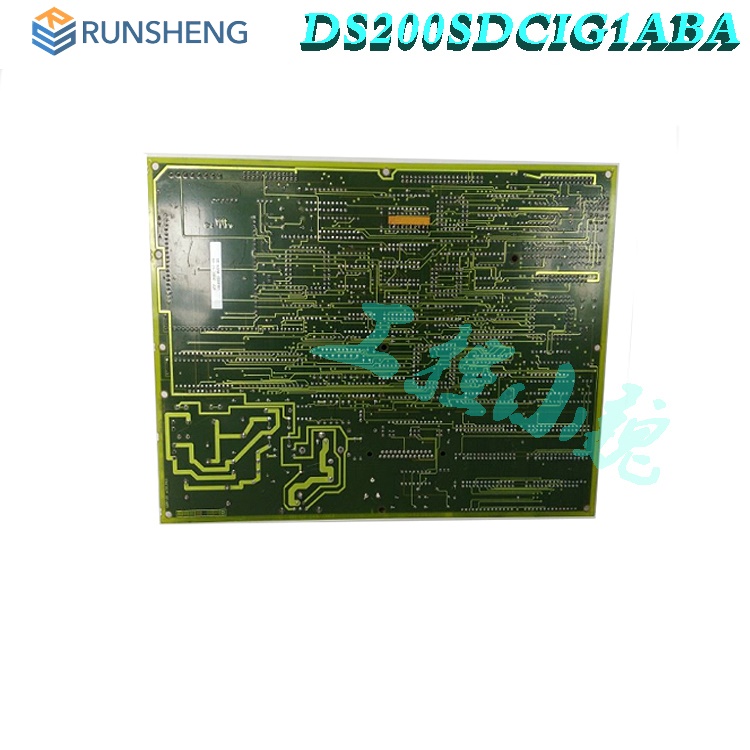
GE DC Power Supply and Instrumentation Board DS200PCCAG1ABB
The circuit board has multiple circuits on its surface, including drive circuits for armature SCR gating and drive circuits for different AC and DC line motor signals. The circuit board also includes a motor excitation power supply circuit. It is designed for DC2000 drivers (up to 600 VAC).
Many products have not yet been launched, please contact us for more products
If the product model does not match the displayed image, the model shall prevail. Please contact us for specific product images, and we will arrange for photos to be taken in the warehouse for confirmation
We have 16 shared warehouses worldwide, so sometimes it may take several hours to accurately return to you. We apologize for any inconvenience caused. Of course, we will respond to your concerns as soon as possible.
DS200PCCAG1ABB
- Power supply
and dashboard are in stock and will be shipped on the same day.
DS200PCCAG1ABB - The power supply and dashboard are in an unused and rebuilt state.
To get the best deals on DS200PCCAG1ABB - power and dashboard, please contact us and we will reply within 24 hours.
Function Description
DS200PCCAG1ABB is a power supply and dashboard developed by GE. It is part of the drive control system. The power supply and dashboard (SDCI) are critical components within the DC2000 drive system, providing critical logic power and interface circuits. This section explores various circuits integrated into SDCI boards and delves into their functions.
Power
supply and monitoring circuit
This board contains a range of power sources, including+5 V DC, 4 A, -15 V DC, 0.4 A, -24 V DC, and 115 V AC, 0.4 A. In addition, it is responsible for monitoring numerous AC lines and DC motor signals, such as armature current and voltage, excitation current and AC line current, voltage amplitude and phase sequence. These monitoring circuits contribute to the comprehensive functionality of the DC2000 drive system.

SDCIG2
board for external magnetic field exciter
The exploration of SDCIG2 revealed its use in applications exceeding 10 A, which require external excitation. The difference between SDCIG2 and SDCI is that some excitation power circuits are omitted.
Power
supply and regulation
The board receives 38 V AC power from the Control Power Transformer (CPT), rectifies and filters it to generate unregulated+24 V DC and -24 V DC outputs. The regulator obtains -15V DC power from a+24V DC power supply. SDCI generates+5 V DC power from a+24 V DC power supply, with a 4 A output, and provides insight into the regulation status through the PSEN signal.

Motor
magnetic field control
The DC2000 driver equipped with this circuit board provides non inverting, non pluggable (NRX) motor magnetic field control. Careful observation reveals that it plays an important role in providing internal 10 A NRX motor magnetic field control, and is equipped with fused magnetic field output, line reactors, and buffer circuits. Visual indicators such as neon lights help quickly identify blown fuses, enabling efficient diagnosis.
On
site power circuit and current VCO
Integrated field power supply circuit for up to 10 A fields. Detailed inspection of the field power supply circuit inside the circuit board, clarifying the inclusion of buffers and reactors. Explored key aspects such as field power input, filtering, and protection mechanisms, enhancing the understanding of the functions of field power circuits.
Features
The DC power supply and dashboard play a crucial role as interfaces for the DC2000 driver, helping to control the operation of the driver. This board not only enhances troubleshooting capabilities, but also improves availability by integrating LED indicator lights related to each fuse. These indicator lights are extremely useful tools that can immediately send a signal when the fuse blows, simplifying the identification of potential problems.
To inspect the circuit board and check if the LED indicator lights are on, specific steps must be followed to ensure safety and accurate assessment. Open the cabinet where the circuit board is installed and visually inspect the LED lights without direct contact, as there may be high voltage present. Any information regarding the identifier of the blown fuse has been carefully recorded.
Subsequently, cut off all power to the driver and test the circuit board to ensure complete power failure. It may take some time for residual power to flow out of the circuit board to minimize the risk of damage. Based on the blown fuse, it may be possible to check for wiring errors or short circuits. If the circuit board has defects, it may need to be removed and replaced.
During the disassembly process, precautions should be taken to prevent contact with other circuit boards or devices in the driver. Plastic buckles that touch panels, cables, or secure circuit boards should be avoided to prevent damage. Be careful to disconnect all cables and pay attention to ribbon cables to ensure a smooth disassembly process without causing unnecessary pressure on the connectors.

It is equipped with Berg type jumpers, named JP. These manually movable jumpers can be used for purposes such as manufacturing testing or accommodating customer options.
Hardware
tips and specifications
Due to the use of multiple unique and important hardware components and component specifications, this DS200PCCAG1ABB printed circuit board has gained the functionality of a DC power supply and an instrument panel. Firstly, this DS200PCCAG1ABB PCB component has many Mark V series standardized voltage limiting hardware components, including various rectifiers, diodes, capacitors, and integrated circuits. In addition, all DDS200PCCAG1ABBhardware components and specifications on its base circuit board are well protected by its thick, basic standard PCB coating, which wraps and protects individual DDS200PCCAG1ABBboard hardware components according to functional priority. In addition, this DDS200PCCAG1ABBproduct component also provides multiple fuses and jumpers; Each application has its own instruction manual to introduce. The fuses in this DDS200PCCAG1ABBprinted circuit board assembly include:
FU1 115 V AC power fuse
FU2 DC signal level power fuse
FU3 DC signal level power fuse
FU5 internal NRX 10 A on-site/MOV component fuse
FU6 internal NRX 10 A on-site/MOV component fuse
All of these fuses listed in the DS200PCCAG1ABB DC power supply and dashboard components are named based on a combination of their originally intended functions and factory printed nomenclature. A total of three jumpers are provided for the assembly of this DS200PCCAG1ABB printed circuit board, including JP1 MD control source jumper, JP2 MA AC contactor release time jumper, and SW1 AC line CT load as a function of nominal DC output current jumper. Like the fuses listed above, these jumpers in the internal components of the DS200PCCAG1ABB printed circuit board are named based on their respective labels and combinations of specific functional selections for larger DDS200PCCAG1ABB boards and Mark V series automatic drives. The jumpers and fuses suitable for the assembly of this DDS200PCCAG1ABBproduct are not physically combined together on the DSDS200PCCAG1ABBCB substrate; But it is applied according to functional needs.
The maintenance and regular upkeep of DS200PCCAG1ABB can only be carried out by qualified personnel. That is to say, due to high voltage in the driver and circuit board, do not attempt to disassemble and replace the circuit board by yourself. If the circuit board comes into contact with components in the drive cabinet, you may inadvertently damage the circuit board, or if cables are removed using incorrect methods, you may damage the cables. You can perform a troubleshooting task yourself. You can open the cabinet and check the LED indicator lights on the circuit board while the drives and circuit boards are powered on. If the LED indicator light is on, it means that the fuse related to the LED has blown. However, you cannot touch any components in the circuit board or driver. If you see a blown fuse and want to remove the circuit board, you must follow these steps. Not only do you have to turn off the drive, but you also have to remove the fuses on the three-phase power supply. Also make sure to remove the auxiliary power supply. Wait for a few minutes to disconnect the power supply from the circuit board. Before continuing, please use testing equipment to verify that there is no power supply in the circuit board.
Frequently
Asked Questions
What is DS200PCCAG1ABB?
It is a power supply and dashboard under the Drive Control series developed by GE.
What are the functions of power supply and dashboard in DC2000 drivers?
It is an important interface for DC2000 drivers, which enables operational control and enhances overall functionality.
How can this circuit board improve its troubleshooting capability?
The circuit board integrates LED indicator lights related to each fuse, greatly improving troubleshooting capabilities. When the fuse blows, these indicator lights will immediately emit a signal to help quickly identify potential problems.
What are the steps to check the circuit board and check if the LED indicator light is on?
To check the circuit board and check if the LED indicator lights are on, follow specific steps to ensure safety and accurate assessment. Open the cabinet where the circuit board is installed, visually inspect the LED lights without direct contact, and record information about the blown fuses.
How to disconnect the power supply on the circuit board during the inspection process?
To disconnect the power supply on the circuit board, all power supplies to the driver must be cut off. The circuit board must be tested to ensure complete power disconnection and may require waiting for a period of time for residual power to exit the board, in order to minimize the risk of damage.
Can the connection on DS200PCCAG1ABB be removed during operation?
No, you should not remove connections or circuit boards from DS200PCCAG1ABB or reinsert it into DS200PCCAG1ABB while it is powered on. If done in this way, it may damage the equipment of DS200PCCAG1ABB.
What is the JP1 jumper on DS200PCCAG1ABB?
The jumper JP1 on DS200PCCAG1ABB is an MD control source jumper that allows the hardware output driven by the MD contactor to be subordinate to the hardware output driven by the MA contactor on DS200PCCAG1ABB. Usually on DS200PCCAG1ABB, the MD contactor drive output is independently controlled by MCP software.
What is DS200PCCAG1ABB used for?
DS200PCCAG1ABB is used to provide logic power and interface circuits for DC2000 drivers with input voltages up to 600 VAC.
All products on this website are special
products, and market prices have been fluctuating,
Please refer to the customer service quotation for details, as the product is new and the price is not genuine,
Please confirm the model, product, price, and other detailed information with customer service before placing an order. The website has been used,
The new one is for sale, please contact customer service for further communication.
Related
product recommendations:
DS200SDCIG2AEB
DS200SDCIG2AHB
DS200SHVMG1AFE
DS200SHVMG1AGE
DS200SI0CG1A6A
DS200SI0CG1AEA
DS200SIOBH1AAA
DS200SIOBH1ABA
DS200SIOBH1ACA
DS215SLCCG1AZZ01A
DS200SLCCG1ACC
DS200SLCCG1AEE
DS215SLCCG1AZZ01B
DS200SLCCG1AEE
DS200SLCCG1AFG
DS215SLCCG1AZZ01A
DS200SLCCG1AFG
DS200TBQDG1AFF
DS200TBQCG1AAA
DS200TCEAG1BNE
more......
PRODUCT TAGS
Shanxi Runsheng Import and Export Co., Ltd
Address: 3301, Building A, Wanda Center, No. 175 Jiefang Road, Xinghualing District, Taiyuan City, Shanxi Province
Google email: wkcarshop666888@gmail.com
Industrial Control Sales Consultant: Amelia
Whatsapp: +86 18030295882

