DS200SDCIG1AFB | GE | Contactor driver board | DS200SDCIG1AFB
The contactor drive board can generate faults through current feedback designed for monitoring. Two types of such faults are IOC or internal overcurrent faults (when the current exceeds 250% of the rated current) and DI/DT faults (when the rated shunt current undergoes a step change of 100% or greater). These are not the only functional failures applicable to this Mark V turbine control system series product, especially considering that a single A-class functional revision may result in significant changes to the specification functionality of General Electric products.

.jpg)
.jpg)
Many products have not yet been launched, please contact us for more products
If the product model does not match the displayed image, the model shall prevail. Please contact us for specific product images, and we will arrange for photos to be taken in the warehouse for confirmation
We have 16 shared warehouses worldwide, so sometimes it may take several hours to accurately return to you. We apologize for any inconvenience caused. Of course, we will respond to your concerns as soon as possible.
DS200SDCIG1AFB
Other names:
Input/output module DS200SDCIG1AFB
DS200SDCIG1AFB Analog Control Board
Interface board DS200SDCIG1AFB
DS200SDCIG1AFB Current Control Board
Function description:
DS200SDCIG1AFB is a contactor driver board manufactured and designed by General Electric, belonging to the Mark V series used in GE Speedtronic control systems. This technology first appeared in the Mark I series launched in the mid to late 1960s. This DS200SDCIG1AFB printed circuit board, also known as the Mark V Turbine Control System Series PCB (as indicated by the full extended series name), is specifically designed for control and management systems of popular and compatible wind, steam,
and
gas turbine automatic drive components; Considering the traditional product line
status of this DS200SDCIG1AFB product, this is somewhat ironic. This DS200SDCIG1AFB
driver/shunt feedback board is not the original product of its original Mark V
series feature, as it edits the original DS200SDCIG1AFB printed circuit board by
having a unique A-grade feature product revision. The existing shunt feedback
amplifier circuit can also be referred to as series derived shunt feedback or
current shunt reverse feedback. In this setting, the feedback network captures a
portion of the output current and generates a feedback voltage that operates in
parallel with the input signal voltage. When feedback transfers input, the input
impedance will decrease due to feedback. On the contrary, due to the feedback
network being connected in series with the output, the output impedance will
increase.
The feedback here is from the emitter of the second stage through resistor Rf to the base of the first stage. Due to the amplification effect of transistor Q1, the input voltage (Vin2) of the second stage is much larger than the input voltage (Vin1) of the first stage, and is in phase opposite to the input voltage of the first stage (i.e., with a phase difference of 180 °).
Due to the effect of the emitter follower, the voltage Ve2 is only slightly lower than Vin2. Moreover, the voltages Ve2 and Vin2 are in phase. Therefore, the amplitude of Ve2 is greater than Vin1, and the phase difference with Vin1 is 180 °. When the input signal increases causing an increase in Is, the feedback current If will also increase, so the input current Vin1 will be smaller than the current without feedback because it is the difference between Is and If. Therefore, negative feedback is provided.
Hardware
tips and specifications
DS200SDCIG1AFB is a square circuit board typically used for any Mark V series circuit board product, storing all its hardware components by connecting them to its base circuit board. As a driver shunt card, the DS200SDCIG1AFB board can generate faults through current feedback designed for monitoring. Two types of such faults are IOC or internal overcurrent faults (when the current exceeds 250% of the rated current) and DI/DT faults (when the rated shunt current undergoes a step change of 100% or greater). These are not the only functional failures applicable to this Mark V turbine control system series product, especially considering that a single A-class functional revision may result in significant changes to the specification functionality of General Electric products. The DS200SDCIG1AFB printed circuit board product provided by General Electric, as a traditional series product, does not provide a large amount of original instruction manual materials online. In view of this, the DDS200SDCIG1AFB functional product number itself can be regarded as a powerful primary source of general hardware information for the DDS200SDCIG1AFBmotherboard, encoding various hardware components and specifications with a series of functional naming blocks. For example, the DSDS200SDCIG1AFBunctional product number begins with a dual function DS200 series label, which describes the normal Mark V series assembly of the DSDS200SDCIG1AFBCB and its domestic original manufacturing location.
Other
relevant details revealed through the DS200SDCIG1AFB functional product number
include the following for this DS200SDCIG1AFB PCB:
DSFB Function Product Abbreviation
Group 1 Mark V Series Product Grouping
Ordinary PCB coating style
Revision of A-class functional products
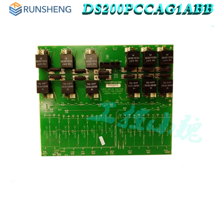
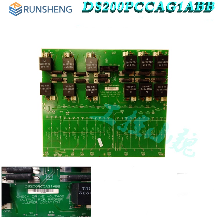
A transformer is installed near one edge of DS200SDCIG1AFB. There are multiple transistors, vertical pin connectors, plug-in connectors, and over ten holes surrounded by conductive materials on the circuit board. These holes are used for connecting the gate and emitter of the connector device. Other available components on this DS200SDCIG1AFB model substrate include integrated circuits, LED indicator lights, resistor network arrays and varistors, as well as resistors and capacitors. The two edges of the DS200SDCIG1AFB circuit board are marked with the positions where reinforcement ribs should be installed. There are drilled holes in the corners for easy installation, and two edges are also marked for alignment during this process. Although there doesn't seem to be a large number of original, factory printed instruction manuals online that provide detailed information about this DS200SDCIG1AFB driver/shunt feedback board, its functional DS200SDCIG1AFB product number alone contains a wealth of valuable information, including its Mark V series assembly, DSFB functional abbreviations, normal printed circuit board coating styles, its first Mark V series grouping, and its unique A-level functional revisions.
Common
problems:
What is a contactor driver board?
The contactor driver board is an electronic circuit board used to control and drive contactors. A contactor is an electromechanical switch used to switch power circuits.
How does the contactor drive board work?
The contactor drive board receives signals from the control system and uses these signals to power on or off the contactor coil. This in turn will open or close the contacts of the contactor, allowing or interrupting the flow of current.
What are the main characteristics of the contactor drive board?
The functionality may vary, but common features include input signal compatibility, protection mechanisms, status indicators, and compatibility with different types and sizes of contactors.
What type of component is used for the DS200SDCIG1AFB driver/shunt feedback board?
The DS200SDCIG1AFB driver/shunt feedback board uses ordinary Mark V series components, and its DDS200SDCIG1AFBfunctional product number contains the DS200 series label.
Is this DS200SDCIG1AFB circuit board covered by any warranty protection after my purchase?
Yes, it is. After your first purchase of this DS200SDCIG1AFB driver/shunt feedback board, it will come with a one-year warranty protection.
What does the normal PCB coating style of this DS200SDCIG1AFB driver/shunt feedback card represent?
The normal PCB coating used on this DS200SDCIG1AFB driver/shunt feedback card is a thick basic protective layer, which does not fully cover all hardware components on the DS200SDCIG1AFB board, but instead provides a solid protective foundation for more important components.
All products on this website are special
products, and market prices have been fluctuating,
Please refer to the customer service quotation for details, as the product is new and the price is not genuine,
Please confirm the model, product, price, and other detailed information with customer service before placing an order. The website has been used,
The new one is for sale, please contact customer service for further communication.
Related
product recommendations:
DS200PCCAG7ACB
DS200CPCAG1A
DS200SHVIG1B
DS200SHVIG1BHD
DS200EXPSG1A-CB
DS200FCRLG1AFC
DS200DSPCH1AEA
DS200EXPSG1A
DS200KLDCG1AAA
DS200FHVAG2ACA
DS200SDCCG1AHD
DS200UCIAG1ACB
DS200CTBAG1ADD
DS200SDCCG1ACA
DS200FECBG1AAA
DS200VPBLG1ADD
DS200GDPAG1ALF
DS200UCPBG5AFB
DS200SDCCG1AEB
DS200FCSAG1A-CB
DS200LPPAG1AAA
DS200DMCAG1AJD
DS215DMCAG1AZZ02A
DS200DMCCBG1AKG
DS200LDCH1APA
DS200SHVMG1AED
more......
PRODUCT TAGS
PLC Dragon Automation
Address: Wanda Plaza, Chengdu, Sichuan Province
Google email: wkcarshop666888@gmail.com
Industrial Control Sales Consultant: Amelia
Whatsapp: +86 18030295882
12A3256BC9DA41BAB264DB676273DA32.png)


3BE7E049824E4F11BE61AD65D86DFEBD.png)