DS200SDCCG1ACA | GE | Contactor control board | DS200SDCCG1ACA
General Electric's Mark V is a series of control and management systems, as well as automatic drive components and parts, designed for use in various compatible configurations of steam, gas, and wind turbines. This Mark V series is considered a traditional series because its original retailers are no longer actively producing it, and it is one of the last General Electric Mark product lines to utilize its patented Speedtronic technology.

.jpg)
.jpg)
Many products have not yet been launched, please contact us for more products
If the product model does not match the displayed image, the model shall prevail. Please contact us for specific product images, and we will arrange for photos to be taken in the warehouse for confirmation
We have 16 shared warehouses worldwide, so sometimes it may take several hours to accurately return to you. We apologize for any inconvenience caused. Of course, we will respond to your concerns as soon as possible.
DS200SDCCG1ACA
Other names:
Input/output module DS200SDCCG1ACA
DS200SDCCG1ACA Controller module
Interface board DS200SDCCG1ACA
Function
description:
The DS200SDCCG1ACA printed circuit board product from General Electric was originally manufactured for placement in its Mark V series, as described above. General Electric's Mark V is a series of control and management systems, as well as automatic drive components and parts, designed for use in various compatible configurations of steam, gas, and wind turbines. This Mark V series is considered a traditional series because its original retailers are no longer actively producing it, and it is one of the last General Electric Mark product lines to utilize its patented Speedtronic technology.
This
DS200SDCCG1ACA printed circuit board, or PCB for
short, can be better defined as a contactor guide card through its official
functional product description, as it appears in the original General Electric
or Mark V Turbo Control System series
instruction manual documentation. Although this DDS200SDCCG1ACAPCB can certainly
be defined as a contactor guide card, it is not an original Mark V series
product with this specific function; That will be the revised version of the
A-grade functional product of DDS200SDCCG1ACA which is missing from the guidance
card of the parent contactor of DS200CPCAG1. To control the opening and closing
of the contactor, the CDBA board provides power. 115 V is the coil voltage of
the contactor used with CPCA. CPCA converts the input 115V AC power
into 105V DC power
to drive the contactor coil. When it is necessary to close and keep the
contactor closed, the CPCA card (rather than the CDBA board)
provides all voltage.
Hardware
tips and specifications
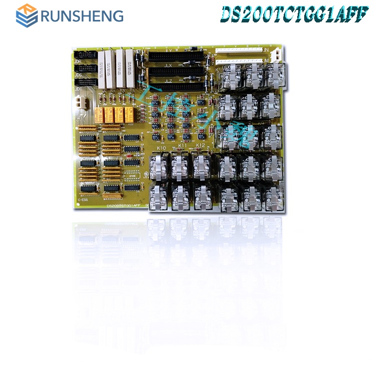
As mentioned above, the hardware components and component specifications of this DS200SDCCG1ACA contactor control card are already very high, and the only functional product revision it contains further enhances this performance. The GE contactor control board DDS200SDCCG1ACAhas one 12 pin connector and two 2-pin connectors. It also has four wiring terminals that can connect up to twelve signal wires.
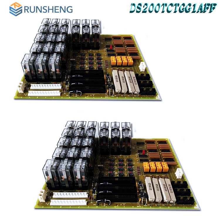
The
GE contactor control board DS200SDCCG1ACA is also equipped with a 24VDC socket
power relay. Due to the wiring terminals on the circuit board, maintenance
personnel must remove the wires connected to the terminals, which will require
special consideration, as described in the original Mark V Turbo Control System
series instruction manual document. The wiring terminals of DS200SDCCG1ACA PCB
enable signal cables to be connected to the circuit board for processing; Some
wires extending from these terminal blocks transmit signals from the circuit
board, while others receive signals processed by the DS200SDCCG1ACA circuit board.
Unfortunately, this DS200SDCCG1ACA contactor control card is not the most
customizable model among General Electric printed circuit boards, as it does not
have a single manually movable hardware jumper during assembly. As defined again
in the original General Electric manual material, the function of the
DS200SDCCG1ACA contactor control card is very similar to that of the CDBA board,
which is another new or refurbished product that can currently be repaired or
replaced at Control. The DDS200SDCCG1ACAcontactor control card and similar CDBA
boards provide power to
facilitate the opening and closing of contactors in the Mark V series.
General Electric provides a series of carefully crafted instructions for establishing terminal connections with the DS200SDCCG1ACA printed circuit board. Carefully insert the screwdriver, release one of the terminals without touching other components, and unplug the wire. Perform the same operation on all fixed wire terminals. Grasp the cable of the connector and pull it out of the connector on the circuit board. Stabilize the circuit board with an empty hand. This is important because the socket power relay is located on the DS200SDCCG1ACA circuit board and may be damaged when tightening terminals, connecting cables, and securing the circuit board; Relays have moving parts, and any vibration can damage the relay. All hardware components and component specifications detailed in the DS200SDCCG1ACA contactor navigation card mentioned above should receive at least some form of protection and insulation from the normal style of General Electric printed circuit board coating, which has been applied to various hardware components during assembly according to functional priority. The performance specifications and dimensions initially introduced for this DS200SDCCG1ACA PCB were undoubtedly affected by the revision of A-class functional products.
Test
point:
CPH-CPCA power supply positive input test point. All testing measurements must be conducted using isolated testing equipment capable of measuring floating potential, as CPH does not reference the common level of the driver.
CPN - CPCA power supply negative input test point.
PSP - PSP test point for positive input of CPCA coil.
PSN - For CPCA coil control negative input, there is a PSN test point.
Adjustable hardware board:
JP1:
JP1-2-3 can reduce the output ratio of factory card testing. If factory card testing is not conducted, JP1 must be 1-2. 1.2.1 is normal operation. The special setting for factory card testing is 2.3.
Factory testing jumper
JP2:
Allow multiple CDBA boards to coordinate operations
To coordinate functionality, connect 1 TB9 and -10 to parallel voltage (2.3 positions).
In order to supply power to the 12 circuits in the circuit, a 24V power supply and a 340 ohm series connection were used.
If all 12 CDBA inputs are connected together, all contractors can pick up and drop off simultaneously.
1.2 Normal non coordinated CDBA operations.
2.3 Collaborative operation
RV1:
Coil current reference potentiometer Pot.
Use test points REFA and ACOM to adjust the current of the driving contactor coil in RV1.
This potentiometer is predetermined in the factory and varies according to the specific contactor that needs to be driven.
Features:
There is a 12 pin connector and two 2-pin connectors on the motherboard. It also has four wiring terminals that can connect up to twelve signal wires.
The GE contactor control board also includes a 24VDC socket power relay. The CPCA card does not include adjustable hardware.
The wiring terminal allows signal lines to be connected to the circuit board and processed. Some wires transmit signals from the circuit board. Other wires transmit signals to the circuit board and then process them.
To determine which terminal to connect the wire to, use an identifier. Ensure that the wires are not loose, but do not tighten them too tightly to prevent damage to the wires or terminal screws.
When inserting the circuit board into the cabinet and moving it into place, ensure that the relay does not hit any metal structures or other components in the drive.
Relays are the main components on circuit boards and are prone to damage due to rough handling.
Common
problems:
How to check the price and supply of contactor test boards?
Please contact Amelia for sales at+86 18030295882 or request a quote.
What payment methods do you accept?
Bank transfer is the preferred payment method. If you need more payment methods, please contact us.
How are the circuit boards we ship packaged?
Place the parts in the anti-static bag and safely pack them in the ESD box with ESD foam pad to protect the electrical components.
How big is DS200SDCCG1ACA?
The width of DS200SDCCG1ACA is 4 inches. The height of DS200SDCCG1ACA is 3.5 inches.
What applications is DS200SDCCG1ACA used for?
DS200SDCCG1ACA is used for EX2000 drive applications, which means that DS200SDCCG1ACA is used together with a digital generator exciter.
All products on this website are special
products, and market prices have been fluctuating,
Please refer to the customer service quotation for details, as the product is new and the price is not genuine,
Please confirm the model, product, price, and other detailed information with customer service before placing an order. The website has been used,
The new one is for sale, please contact customer service for further communication.
Related
product recommendations:
DS200EXDEG1ABA
DS200DACAG1ACD
DS200ACNAG1A
DS200TCDAH1BHD
DS200TCDAG2BCB
DS200GLAAG1ACC
DS200RTBAG2AHC
DS200TCQCG1BBA
DS200IIBDG1AGA
DS200QTBAG1ACB
DS200TCQBG1B
DS200TBQCG1AAA
DS200RTBAG3AGC
DS200FCSAG2A-CB
DS200PCCAG6A
DS200TCQBG1BCA
DS200UDSAG1ADE
DS215SLCCG1AZZ01A
DS200RTBAG3AHC
DS200FCGDH1BBA
DS200IIBDG1ADA
more......
PRODUCT TAGS
PLC Dragon Automation
Address: Wanda Plaza, Chengdu, Sichuan Province
Google email: wkcarshop666888@gmail.com
Industrial Control Sales Consultant: Amelia
Whatsapp: +86 18030295882
12A3256BC9DA41BAB264DB676273DA32.png)


3BE7E049824E4F11BE61AD65D86DFEBD.png)