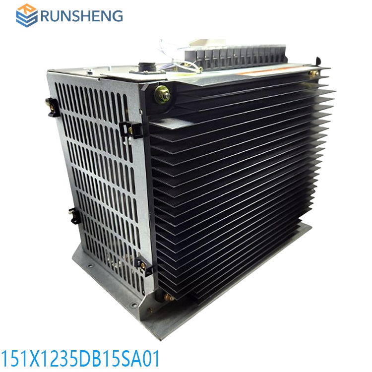
151X1233DB01SA01R | EX2100E Regulator PCM | GE | 151X1233DB01SA01R
The EX2100E control software supports high performance and helps customers and field engineers understand, install, commission, adjust and maintain excitation control systems. The exciter software is configured and loaded through the ToolboxST application and resides in the controller. The software is represented on the ToolboxST component editor screen by control blocks, which are connected to each other to show the signal flow.
Many products are not yet on the shelves, please contact us for more products
If the product model is inconsistent with the display picture, the model shall prevail. Please contact us for specific product pictures, and we will arrange to take photos in the warehouse for confirmation
We have 76 shared warehouses around the world, so sometimes it may take several hours to accurately return to you, please understand. Of course, we will respond to your concerns as soon as possible.
151X1233DB01SA01R Other names:
Editable controller 151X1233DB01SA01R
151X1233DB01SA01R Input and output unit
Excitation control unit system 151X1233DB01SA01R
Dual Control (Power Bridge Warm Backup)
The EX2100e regulator system offers a warm backup (WBU) configuration that includes dual exciter control I/O and protection. The control consists of M1 (Master One) and M2 (Master Two) with two IGBT bridges that can accept separate or shared AC input power. The control configuration can also share a common DC output circuit to the exciter field through a transfer module. M1 and M2 are independent controllers, each with automatic and manual regulator functions. Either M1 or M2 can control bridge firing, as determined by the operator. In the WBU configuration, M1 controls bridge #1 and M2 controls bridge #2.
.jpg)
To handle the application software, two independent Universal Controller Standalone Board Version B (UCSB) controllers with separate PCMs and output selector modules (SCM or TCM) provide DC output current for the exciter field (or SCT control winding).
The active power bridge receives gating commands from the active control (M1 or M2) and supports the full field voltage and current requirements of the exciter field when the gating circuit of the standby power bridge is inhibited. The operator has full control over selecting which of the dual power bridges is active or inactive. Bidirectional bumpless transfer between the active and inactive bridges is standard. The active master can also self-diagnose faults or missed operations and activate the standby control and power bridges without operator intervention.
Control Cabinet
The EX2100e regulator system is enclosed in a NEMA® 1/IP20 or IP21 freestanding indoor metal cabinet for floor mounting. An IP54 cabinet option is also available. The standard color of the cabinet exterior is ANSI-70 (light gray) (other colors available). The interior is galvanized steel. The equipment is designed to operate in an ambient temperature range of 0 to 40°C (32 to 104 °F). Depending on the specific application, current derating factors may apply at 50°C (122 °F).
.jpg)
Power Conversion Module
The Power Conversion Module (PCM) consists of an integrated IGBT inverter module that contains six IGBTs connected in a three-phase inverter configuration. Two of the six IGBTs are used to create a PWM DC output for excitation. The third IGBT is used to discharge the DC link capacitor into an external DD resistor to prevent overvoltage.
The input power can be rectified AC, DC from the station battery, or both. In dual redundant applications, there is a primary control and PCM (M1) and a backup control and PCM (M2) that are identical. The transfer module evaluates the health of the primary and backup controls and selects which control is active to provide maximum reliability and availability.
Control Software
The 151X1233DB01SA01R EX2100e control software supports high performance and helps customers and field engineers understand, install, commission, adjust and maintain the excitation control system. The exciter software is configured and loaded from the ToolboxST application and resides in the controller. The software is represented on the ToolboxST component editor screen by control blocks, which are interconnected to show the signal flow.
The generator voltage and current from the PTs and CTs are the source of the control signals required for the automatic (generator terminal voltage) regulator, most limiters and protection functions. They are connected to the ESYS, which acts as a signal conditioner to isolate and scale the signal. The conditioned signal is fed to the controller. The system simultaneously samples the AC waveform at high speed and uses advanced mathematical algorithms to digitally generate the required variables.

The output of the software sensor system includes the following:
Generator voltage
Generator active current (phase average in watts)
Generator reactive current (phase average in reactive power, VARs)
Generator frequency (current)
Slip (signal indicating rotor speed change)
The sensor system uses the output to calculate the following:
• Generator power and VARs
• Generator flux (V/Hz)
• Phase angle and power factor
All products on this website are special products, and market prices are always fluctuating.
The specific quotation is subject to customer service, because the product is new and the price is not real.
Please confirm the model and product, price and other details with customer service before placing an order. The website has been used.
New ones are on sale, please contact customer service for communication.
Recommended products:
IC695ALG508-AA
IC3500A452L208
DS3800HFPB1F1E
DS3800NB1F1B1A
DS3800DIC1D1B
IS210BPPBH2BMD
DS3800HI0C1L1H
DS3800HIOC
DS3800HFPB1F1E
IS200WREAS1ADB
IS200AEPAH1ACB
IS200AEPAH1AFD
IS210MACCH2AGG
IS210MACCH2AEG
IS200AEPCH1ABC
IS200BPPBH2CAA
More......
PRODUCT TAGS
Shanxi Runsheng Import and Export Co., Ltd
Address: 3301, Building A, Wanda Center, No. 175 Jiefang Road, Xinghualing District, Taiyuan City, Shanxi Province
Google email: wkcarshop666888@gmail.com
Industrial Control Sales Consultant: Amelia
Whatsapp: +86 18030295882

