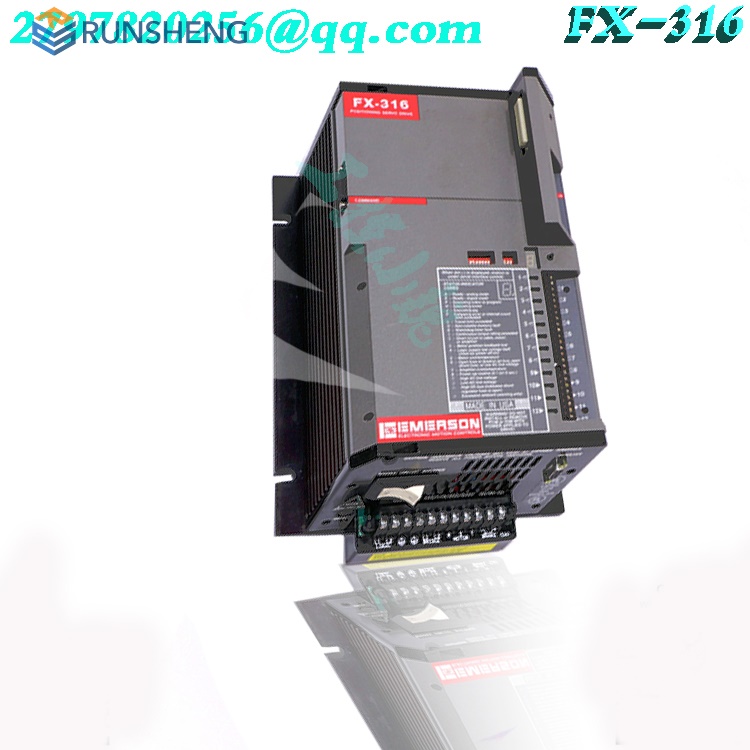
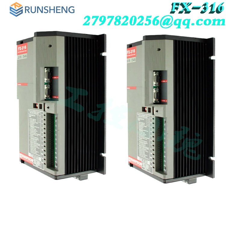
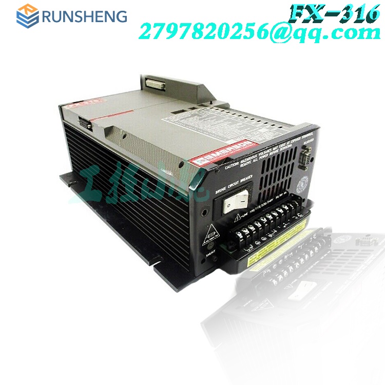
EMERSON SERVODRIVE FX-316
The basic drive provides up to thirty-two different moves or “indexes” that can be pre-programmed using PCX user interface software. All parameters are stored in the FX drive’s non-volatile memory. Each index is a complete and unique motion sequence. Commands to start these indexes plus other commands such as Stop, Jog and Home may be input from a Programmable Logic Controller (PLC), an operator interface or through serial communications. Setup of the I/O functions is fully explained in the “PCX Software Setup and Operation” section of this manual. Serial commands are listed in the FX Drives Serial Commands Manual (P/N 400255-00).
.jpg)
.jpg)
All products on this website are special products, and market prices have been fluctuating,
The specific customer service quotation shall prevail, as the product is a new one and the traps are not real,
Please confirm the model, product, price, and other detailed information with customer service before placing an order. The website has been used,
The new one is for sale, please contact customer service to communicate.
Basic Motion Control
A motion control system provides programmable control of speed and positioning of motors. Controlling motion includes the ability to accelerate and decelerate, control the velocity and achieve accurate positioning of the motor shaft. An EMERSON Motion Control System consists of an FX Positioning Drive, which includes the microprocessor controlled amplifier, a DX (230V) Series Brushless Servo Motor of correct torque rating, and motor cabling as shown in Figure 1, “Basic FX Drive,” on page 1.

The basic drive provides up to thirty-two different moves or “indexes” that can be pre-programmed using PCX user interface software. All parameters are stored in the FX drive’s non-volatile memory. Each index is a complete and unique motion sequence. Commands to start these indexes plus other commands such as Stop, Jog and Home may be input from a Programmable Logic Controller (PLC), an operator interface or through serial communications. Setup of the I/O functions is fully explained in the “PCX Software Setup and Operation” section of this manual. Serial commands are listed in the FX Drives Serial Commands Manual (P/N 400255-00).
Serial Communications
The FX drive is capable of two-way communication with an external controller or computer using an optically isolated RS-423 serial interface port. RS-423 is signal compatible with both RS-232C and RS-422 serial communications protocol. Programming of motion parameters, input/ output functions, operating modes, indexes, and setup parameters can be accomplished through this serial interface port. Amplifier status and motor position information is also available through serial communications.The serial interface may be used as a “real-time” control interface. However, due to transmission time, consideration must be given to system performance requirements prior to applying this method for real-time control. Stop commands, for example, may not be executed fast enough. Multi-drop serial cables can be used to connect up to thirty-one (31) drives to a single COM port. In a multi-drop setup, each drive must have a unique axis identifier code. The identifier codes are set using DIP switches on the front panel. An example of a multi-axis connection is shown in Figure 5, “Serial Communication Multi-Drop Setup,
Input/Output Functions
The FX drive is equipped with eight optically isolated input lines and four optically isolated output lines. Each input and output line has two screw terminals associated with it. The first eight pairs of terminals, numbered 1 through 8, are inputs and the last four pairs of terminals, numbered 9 through 12, are outputs. Each of these I/O lines can be configured to perform a variety of motion control functions. These I/O functions are assigned to the I/O lines using PCX, user interface software, used to configure the FX drive. Setup of the I/O functions is explained in the “PCX Software Setup and Operation” section of this manual.These inputs and outputs can connect to a PLC, limit switches, or switches and indicators on an operator’s control panel. An LED indicator associated with each input and output provides visual feedback of I/O activity.
On-line Operations (COM1 - COM4)
The On-line Operations options require serial communications between the personal computer and the FX drive. When you select On-line Operations options for the first time, PCX will attempt to communicate by transmitting a character and then receiving the echo. When the echo is the same as the character transmitted then communications have been established.
PCX tries this procedure with all the possible baud rates (300 to 19,200). Once PCX has established communications, the program will continue by displaying the On-line Operations options. This procedure will not be called again unless communications are disrupted.When you have established serial communications with the FX drive, the On-line Operations menu will be presented on the screen. The axis identifier, drive model and application module (if applicable) are displayed after the screen title at the top of the screen
When PCX is communicating with an FX drive, a busy message appears in the upper left hand corner of the screen. A small “pinwheel” rotates as serial commands are sent and received by the computer. This feature is here to let you know that PCX is operating and transferring data with an FX drive
Drive Setup - Preliminary Data
Before you set up your FX drive using PCX, you need to know some specific details about your system and make some calculations based on your system configuration. Be sure you know the following system details before starting:
1. System configuration - If you are using a gear reducer, leadscrew or belt and pulley, you will need to know the ratio of motor turns per actuator turns. For example, a 10:1 gear reducer, a 2:1 belt and pulley, or a 0.2 in/rev lead screw.
2. User units - Units of measure (distance and velocity) your system operates with; Distances - inches (in), feet (ft), degrees (deg), etc.; Velocities - inches per second (ips), feet per minute (fpm), degrees per second (dps), etc
3. Mechanical limitations of your system - distance limits, torque limits and maximum safe speed (velocity in user units).
For example, in Figure 63, “FX Drive System Example,” on page 74 below you would need to know the following information; gear reducer ratio, lead screw ratio, user units that you want the system to operate with, distance the table can travel and velocity at which the table can safely travel.
Drive Setup - On Screen
When you select the Drive Setup option, the Drive Setup menu will be displayed on the screen. In the Drive Setup Menu, you can access three areas.
The Define Motion menu deals with motion related parameters. Data entry screens for Jog, Home, and Index are available here. The second option, Programming, deals with programming the amplifier. The third option, Drive Configuration, deals with Drive Parameters, Input and Output Functions and Limits.
Many products have not been listed yet. For more products, please contact
us
If the product model is inconsistent with the displayed image, the model shall prevail. Please contact us for specific product images, and we will arrange for photos to be taken and confirmed in the warehouse
We have 16 shared warehouses worldwide, so sometimes it may take several hours to accurately return to you. We apologize for any inconvenience caused. Of course, we will respond to your concerns as soon as possible.
Warehouse discount product recommendation:
XVC768115 3BHB007211R115
BENTLY 3500/60 163179-01
BENTLY 3500/60
EPRO MMS3120/022-000
EPRO CON021
EPRO CON011 9200-00001
MERSON VE3005 KJ2003X1-BA2
EMERSON VE3005
EMERSON SE4308T01
EMERSON SE4301T02
ABB Line differential protection RED670 SF1404859597503 Pre-configured
ASF THOMAS 70050409 VACUUM PUMP
BERGER LAHR stepper motor WPM311.03400
IS200WPDFH1ACB GE
PRODUCT TAGS
PLC Dragon Automation
Address: Wanda Plaza, Chengdu, Sichuan Province
Google email: wkcarshop666888@gmail.com
Industrial Control Sales Consultant: Amelia
Whatsapp: +86 18030295882
12A3256BC9DA41BAB264DB676273DA32.png)


3BE7E049824E4F11BE61AD65D86DFEBD.png)